How to Use Pilot Lamp Red: Examples, Pinouts, and Specs
Introduction
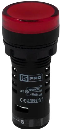
A pilot lamp is an indicator light that shows the status of an electrical circuit or device. The red color typically indicates a warning or that the device is in an active state. Pilot lamps are essential components in various applications, providing visual feedback to users about the operational status of equipment.
Explore Projects Built with Pilot Lamp Red
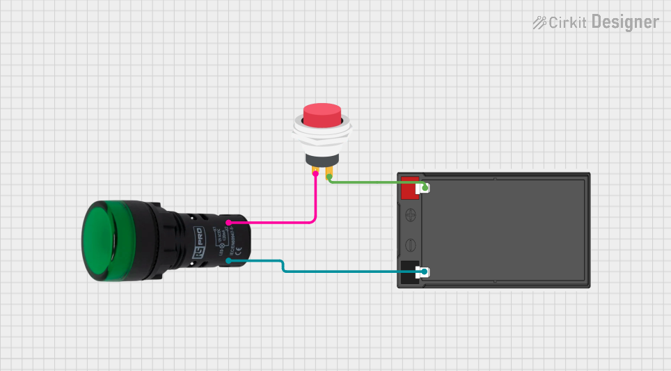
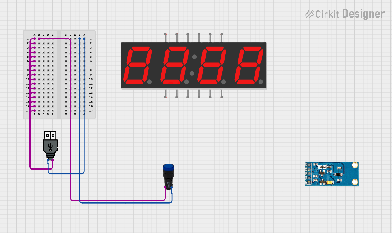
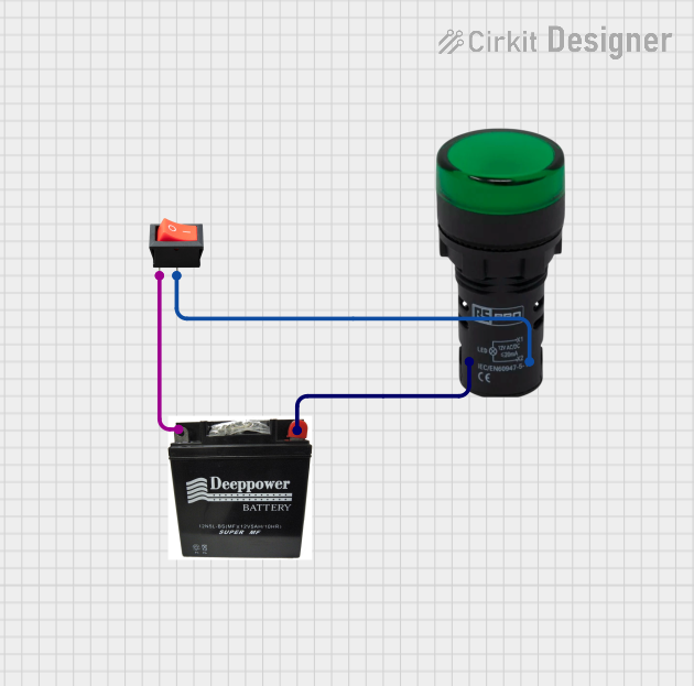
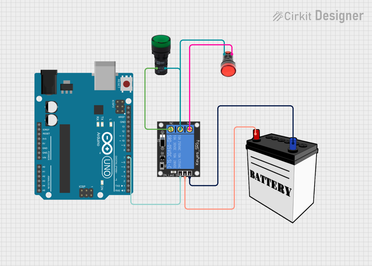
Explore Projects Built with Pilot Lamp Red
Common Applications and Use Cases
- Industrial Control Panels: Indicating the status of machinery and equipment.
- Consumer Electronics: Showing power status or alerts.
- Automotive Dashboards: Indicating warnings or active systems.
- Home Appliances: Signaling operational states or errors.
- Power Distribution Systems: Indicating circuit status.
Technical Specifications
Key Technical Details
| Parameter | Value |
|---|---|
| Operating Voltage | 12V DC |
| Current Rating | 20mA |
| Power Consumption | 0.24W |
| Light Color | Red |
| Mounting Hole Size | 8mm |
| Lifespan | 50,000 hours |
| Operating Temperature Range | -20°C to 70°C |
Pin Configuration and Descriptions
| Pin Number | Description |
|---|---|
| 1 | Positive Terminal (+) |
| 2 | Negative Terminal (-) |
Usage Instructions
How to Use the Component in a Circuit
- Identify the Terminals: The pilot lamp has two terminals: positive (+) and negative (-).
- Connect to Power Source: Connect the positive terminal to the positive side of the power source (e.g., 12V DC) and the negative terminal to the ground.
- Mounting: Secure the pilot lamp in an 8mm mounting hole on your panel or enclosure.
Important Considerations and Best Practices
- Polarity: Ensure correct polarity when connecting the pilot lamp to avoid damage.
- Voltage Rating: Do not exceed the specified operating voltage of 12V DC.
- Current Limiting: Use a current-limiting resistor if necessary to prevent excessive current flow.
- Environmental Conditions: Ensure the operating environment is within the specified temperature range.
Example Circuit with Arduino UNO
To use the pilot lamp with an Arduino UNO, you can connect it to a digital output pin. Below is an example code to turn the pilot lamp on and off.
// Define the pin connected to the pilot lamp
const int pilotLampPin = 13;

void setup() {
  // Initialize the digital pin as an output
  pinMode(pilotLampPin, OUTPUT);
}

void loop() {
  // Turn the pilot lamp on
  digitalWrite(pilotLampPin, HIGH);
  delay(1000); // Wait for 1 second

  // Turn the pilot lamp off
  digitalWrite(pilotLampPin, LOW);
  delay(1000); // Wait for 1 second
}
Troubleshooting and FAQs
Common Issues Users Might Face
Pilot Lamp Not Lighting Up:
- Solution: Check the connections and ensure the correct polarity. Verify that the power supply is providing the correct voltage.
Dim Light Output:
- Solution: Ensure that the power supply is not under-voltage. Check for any series resistors that might be limiting the current excessively.
Flickering Light:
- Solution: Check for loose connections or intermittent power supply issues. Ensure that the power source is stable.
FAQs
Q1: Can I use the pilot lamp with a different voltage?
- A1: No, the pilot lamp is designed for 12V DC. Using a different voltage may damage the component.
Q2: How do I mount the pilot lamp securely?
- A2: The pilot lamp is designed to fit into an 8mm mounting hole. Use the provided nut to secure it in place.
Q3: What is the lifespan of the pilot lamp?
- A3: The pilot lamp has an estimated lifespan of 50,000 hours under normal operating conditions.
Q4: Can I use the pilot lamp outdoors?
- A4: The pilot lamp should be used within the specified operating temperature range (-20°C to 70°C). Ensure it is protected from direct exposure to harsh environmental conditions.
By following this documentation, users can effectively integrate and troubleshoot the Pilot Lamp Red in their projects, ensuring reliable and clear status indication.