How to Use Kontaktor & Tor: Examples, Pinouts, and Specs
Introduction
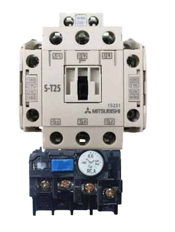
A contactor is an electrically controlled switch designed for switching power circuits. It is widely used in industrial and commercial applications to control high-power devices such as motors, lighting systems, and heating equipment. Contactors are preferred for their ability to handle high currents and provide reliable switching.
The term Tor typically refers to a gate or barrier in electrical contexts. When used alongside contactors, it often represents a mechanism for controlling access or power to specific areas or devices. Together, contactors and Tor systems are integral to automation, safety, and power management in electrical systems.
Explore Projects Built with Kontaktor & Tor


Explore Projects Built with Kontaktor & Tor
Common Applications
- Motor control in industrial machinery
- Lighting control in commercial buildings
- Heating, ventilation, and air conditioning (HVAC) systems
- Power distribution and safety systems
- Automated gate or barrier control in access management
Technical Specifications
Contactor Specifications
| Parameter | Value/Description |
|---|---|
| Operating Voltage | 24V DC, 110V AC, 230V AC (varies by model) |
| Rated Current | 9A to 800A (depending on application) |
| Coil Voltage | 12V, 24V, 48V, 110V, 230V (varies by model) |
| Contact Configuration | SPST, SPDT, DPST, DPDT, etc. |
| Mechanical Life | Up to 10 million operations |
| Electrical Life | Up to 1 million operations |
| Operating Temperature | -25°C to +55°C |
| Mounting Type | DIN rail or panel mount |
Tor Specifications
| Parameter | Value/Description |
|---|---|
| Gate Type | Electromechanical or electronic barrier |
| Control Voltage | 12V DC, 24V DC, or 230V AC |
| Actuation Mechanism | Motorized or solenoid-driven |
| Operating Temperature | -20°C to +50°C |
| Safety Features | Overload protection, emergency stop |
| Integration | Compatible with contactors and relays |
Contactor Pin Configuration
| Pin Number | Pin Name | Description |
|---|---|---|
| 1 | L1 | Input power phase 1 |
| 2 | L2 | Input power phase 2 |
| 3 | L3 | Input power phase 3 |
| 4 | T1 | Output power phase 1 |
| 5 | T2 | Output power phase 2 |
| 6 | T3 | Output power phase 3 |
| A1 | Coil Positive | Positive terminal for the control coil |
| A2 | Coil Negative | Negative terminal for the control coil |
Tor Pin Configuration
| Pin Number | Pin Name | Description |
|---|---|---|
| 1 | Power Input | Power supply for the gate mechanism |
| 2 | Control Signal | Signal input for opening/closing gate |
| 3 | Ground | Ground connection |
| 4 | Safety Input | Emergency stop or safety interlock |
Usage Instructions
Using a Contactor in a Circuit
- Power Supply: Connect the input power phases (L1, L2, L3) to the contactor's input terminals.
- Load Connection: Connect the load (e.g., motor, lighting) to the output terminals (T1, T2, T3).
- Control Circuit: Connect the control coil terminals (A1 and A2) to the appropriate control voltage source.
- Safety Features: Ensure that overload relays or fuses are installed for protection.
- Testing: Test the circuit by energizing the control coil to verify proper operation.
Using Tor with a Contactor
- Integration: Connect the Tor control signal to the contactor's control circuit.
- Power Supply: Provide the required voltage to the Tor mechanism.
- Safety Interlocks: Use the safety input pin to integrate emergency stop functionality.
- Operation: Use the control signal to open or close the gate, which in turn controls the contactor.
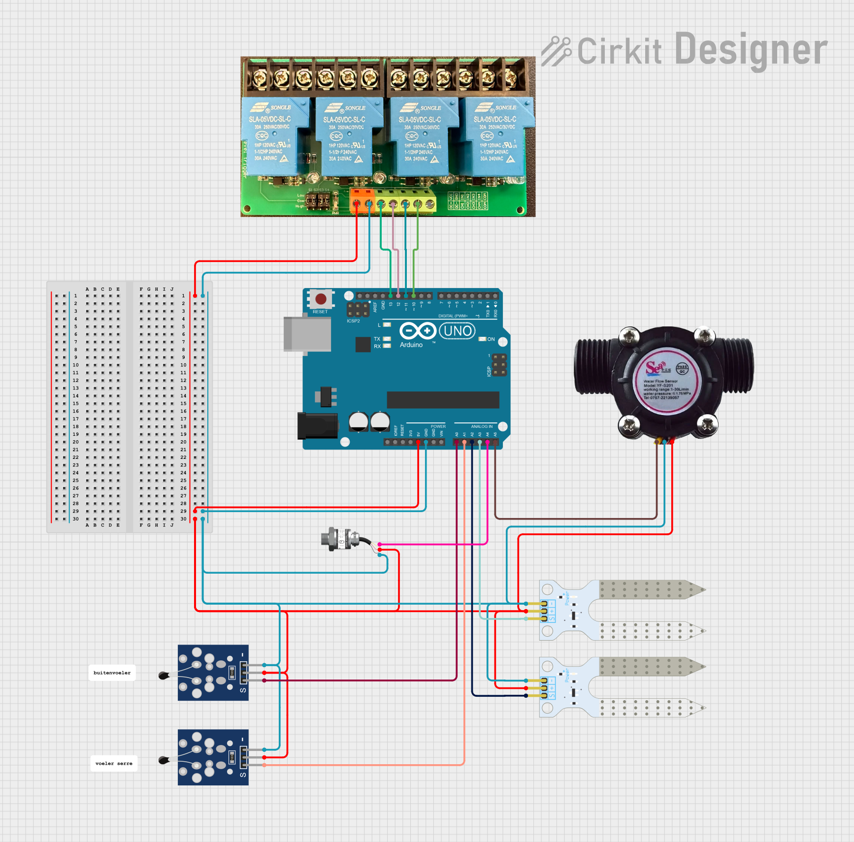
Arduino Example for Contactor Control
Below is an example of using an Arduino UNO to control a contactor via a relay module:
// Define the pin connected to the relay module
const int relayPin = 7;

void setup() {
  pinMode(relayPin, OUTPUT); // Set the relay pin as an output
  digitalWrite(relayPin, LOW); // Ensure the relay is off initially
}

void loop() {
  // Turn the contactor ON
  digitalWrite(relayPin, HIGH);
  delay(5000); // Keep the contactor ON for 5 seconds

  // Turn the contactor OFF
  digitalWrite(relayPin, LOW);
  delay(5000); // Keep the contactor OFF for 5 seconds
}
Best Practices
- Always verify the voltage and current ratings of the contactor and Tor before use.
- Use proper insulation and grounding to prevent electrical hazards.
- Regularly inspect the contactor for wear and tear, especially in high-load applications.
- Ensure that the Tor mechanism is free from obstructions and operates smoothly.
Troubleshooting and FAQs
Common Issues
Contactor Not Switching
- Cause: Control coil not receiving voltage.
- Solution: Check the control circuit and ensure proper voltage is supplied to the coil.
Excessive Heating
- Cause: Overloaded contactor or poor connections.
- Solution: Verify the load current and ensure all connections are secure.
Tor Mechanism Not Operating
- Cause: Faulty control signal or power supply.
- Solution: Check the control signal and ensure the power supply matches the required voltage.
Frequent Tripping
- Cause: Overload or short circuit in the load.
- Solution: Inspect the load and use appropriate overload protection devices.
FAQs
Q1: Can I use a contactor for DC loads?
A1: Yes, but ensure the contactor is rated for DC operation, as DC arcs are harder to extinguish than AC arcs.
Q2: What is the difference between a relay and a contactor?
A2: A relay is typically used for low-power applications, while a contactor is designed for high-power circuits.
Q3: How do I choose the right contactor for my application?
A3: Consider the voltage, current, and type of load (inductive or resistive) when selecting a contactor.
Q4: Can I control multiple contactors with one Tor system?
A4: Yes, provided the Tor system's control signal can handle the combined load of the contactors.
By following this documentation, you can effectively use and troubleshoot contactors and Tor systems in your electrical projects.