How to Use SparkFun Block for Intel Edison - Dual H-Bridge: Examples, Pinouts, and Specs
Introduction
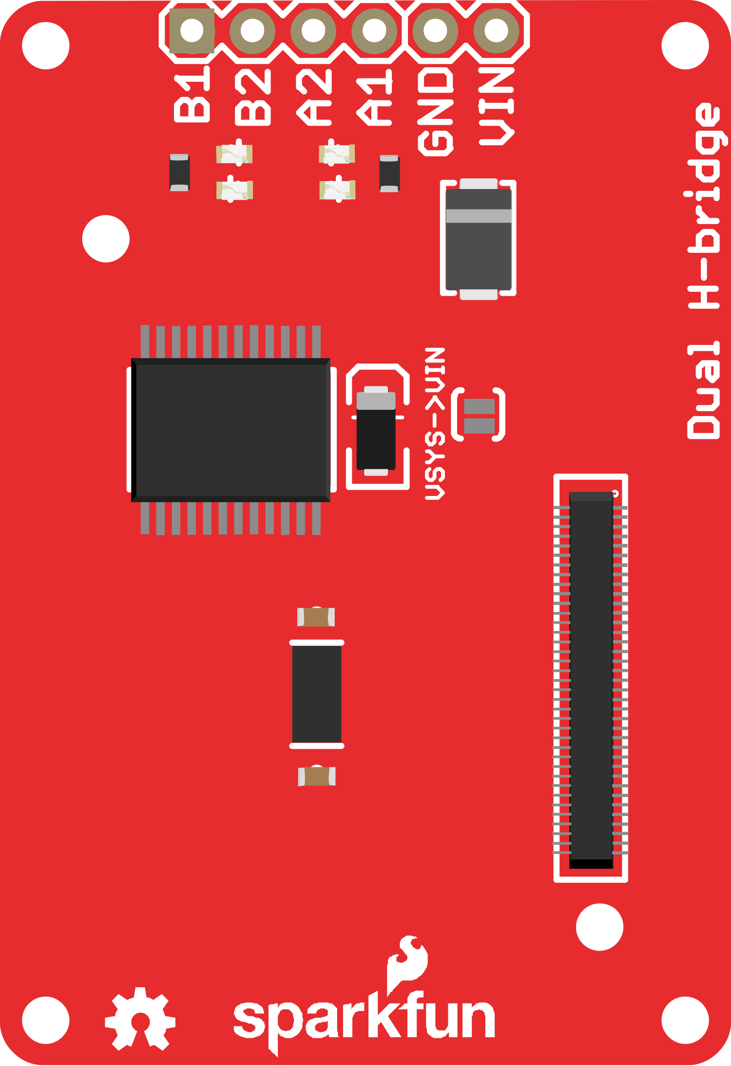
The SparkFun Block for Intel Edison - Dual H-Bridge is a versatile expansion board designed for the Intel Edison development platform. This board is equipped with two H-bridge motor drivers, which enable the control of two independent DC motors or one bipolar stepper motor. Its compatibility with the Arduino IDE allows for seamless programming and integration with other Arduino-compatible shields, making it an ideal choice for robotics projects, prototyping, and educational purposes.
Explore Projects Built with SparkFun Block for Intel Edison - Dual H-Bridge

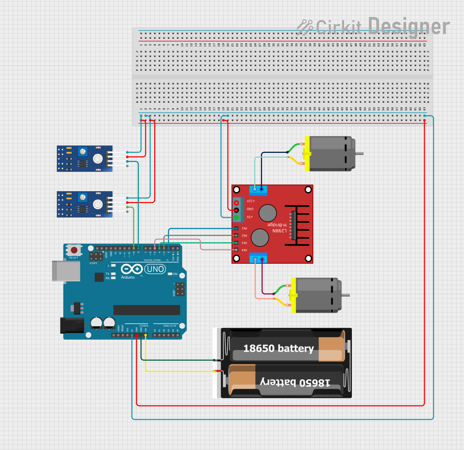
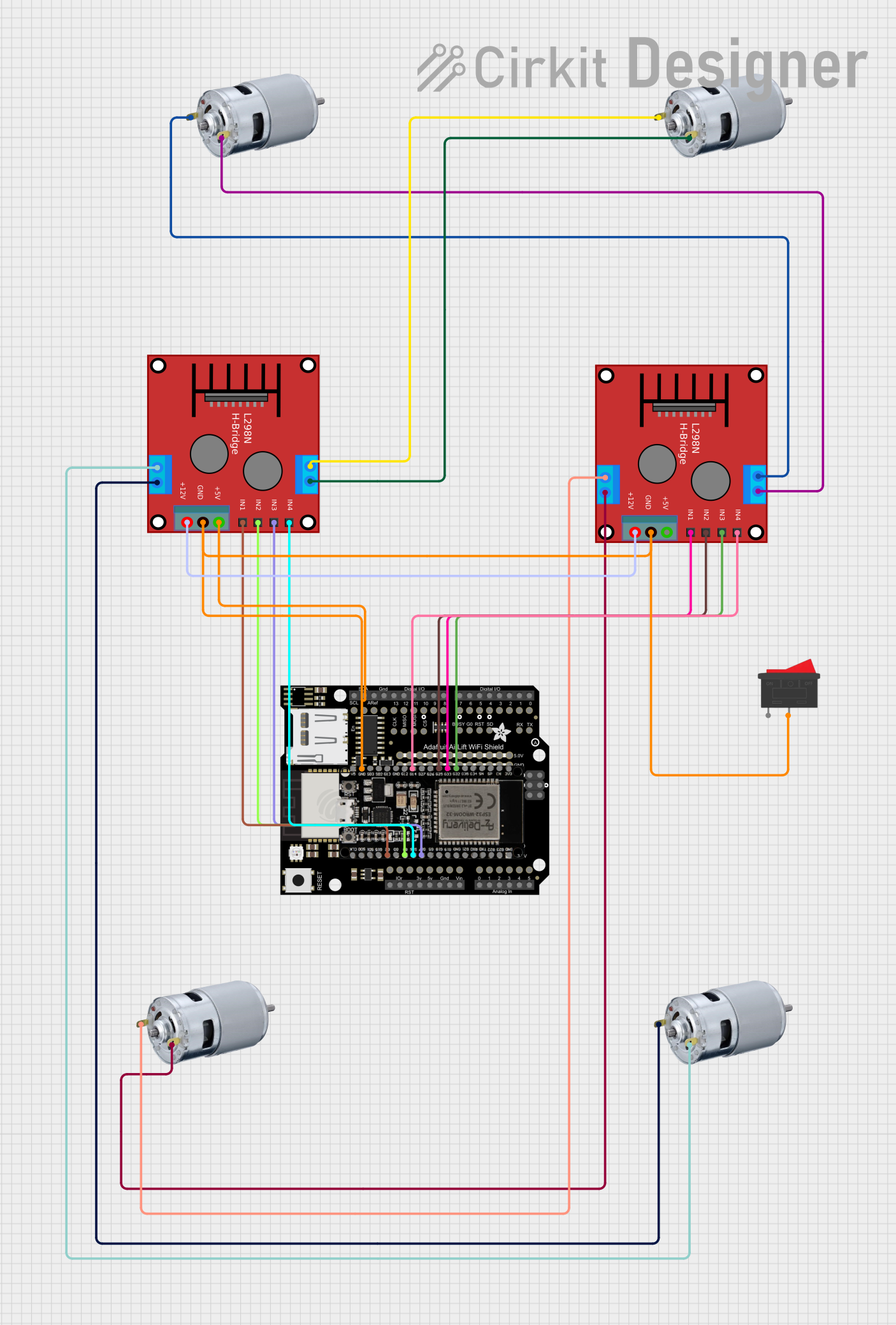
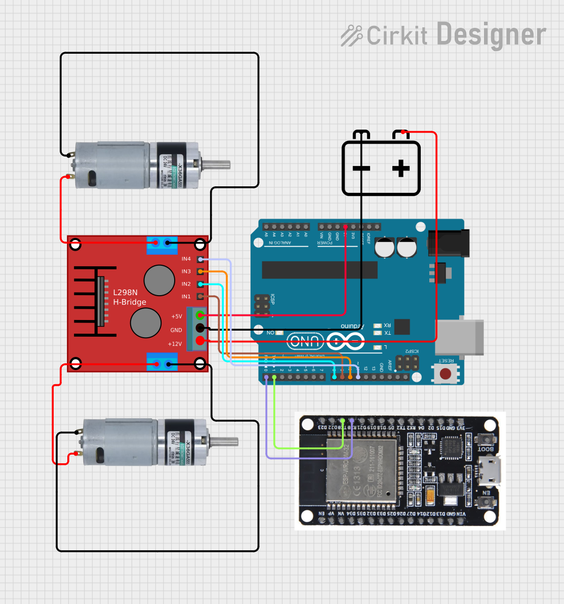
Explore Projects Built with SparkFun Block for Intel Edison - Dual H-Bridge
Common Applications and Use Cases
- Robotics: Drive wheels or actuate robotic arms.
- Prototyping: Quickly implement motor control in your designs.
- Educational Projects: Teach principles of motor control and electromechanics.
- Hobby Projects: Use in RC cars, drones, or custom-built machines.
Technical Specifications
Key Technical Details
- Motor Voltage (VMOT): 6V to 15V
- Logic Voltage (VIO): 1.8V (with Edison), 3.3V or 5V (with Arduino breakout)
- Output Current: Up to 1A continuous per channel
- Peak Current: Up to 2A per channel (short duration)
- PWM Frequency: Up to 20kHz
Pin Configuration and Descriptions
| Pin Number | Description | Notes |
|---|---|---|
| 1 | VMOT (Motor Power Supply) | 6V to 15V |
| 2 | GND (Ground) | |
| 3 | AIN1 (Motor A Input 1) | Logic input |
| 4 | AIN2 (Motor A Input 2) | Logic input |
| 5 | STBY (Standby) | Active-high; low to disable H-bridges |
| 6 | PWMA (PWM for Motor A) | PWM input, up to 20kHz |
| 7 | BIN1 (Motor B Input 1) | Logic input |
| 8 | BIN2 (Motor B Input 2) | Logic input |
| 9 | PWMB (PWM for Motor B) | PWM input, up to 20kHz |
| 10 | AOUT1 (Motor A Output 1) | Connect to motor A |
| 11 | AOUT2 (Motor A Output 2) | Connect to motor A |
| 12 | BOUT1 (Motor B Output 1) | Connect to motor B |
| 13 | BOUT2 (Motor B Output 2) | Connect to motor B |
Usage Instructions
How to Use the Component in a Circuit
- Connect the motor power supply (VMOT) to pin 1 and ground (GND) to pin 2.
- Connect your DC motors to the AOUT1/AOUT2 and BOUT1/BOUT2 pairs for motor A and B, respectively.
- Apply logic voltage (VIO) to the AIN1, AIN2, BIN1, and BIN2 pins to control the direction of the motors.
- Use the PWMA and PWMB pins to apply PWM signals for speed control.
- Ensure the STBY pin is set to high to enable the H-bridges.
Important Considerations and Best Practices
- Always provide adequate cooling for the board when driving motors near the peak current ratings.
- Ensure that the power supply can deliver sufficient current for your motors.
- Use flyback diodes if driving inductive loads to protect against voltage spikes.
- Avoid running motors at stall current as it can quickly overheat and damage the H-bridge.
Troubleshooting and FAQs
Common Issues Users Might Face
- Motor not running: Check if the STBY pin is set to high and that the power supply is correctly connected and turned on.
- Overheating: Ensure proper ventilation and consider adding a heatsink if running motors at high currents for extended periods.
- Erratic motor behavior: Verify that the PWM frequency is within the specified range and that the logic inputs are receiving correct signals.
Solutions and Tips for Troubleshooting
- Double-check wiring and solder joints for any loose connections or shorts.
- Use a multimeter to verify that the power supply is delivering the correct voltage.
- If using PWM, ensure that the duty cycle is set correctly for the desired motor speed.
FAQs
Q: Can I control a stepper motor with this board? A: Yes, you can control a bipolar stepper motor by correctly sequencing the input signals to the H-bridges.
Q: What should I do if the board is not responding to commands? A: Check the power supply, ensure that the STBY pin is high, and verify that the logic signals are being sent correctly from your controller.
Q: Can I use this board with an Arduino? A: Yes, the board is compatible with the Arduino IDE and can be used with Arduino-compatible shields.
Example Code for Arduino UNO
// Example code to control a DC motor with the SparkFun Dual H-Bridge
#include <Arduino.h>

// Define the control pins
const int STBY = 5; // Standby
const int PWMA = 6; // Speed control for motor A
const int AIN1 = 7; // Direction control for motor A
const int AIN2 = 8; // Direction control for motor A

void setup() {
  // Set all the motor control pins to outputs
  pinMode(STBY, OUTPUT);
  pinMode(PWMA, OUTPUT);
  pinMode(AIN1, OUTPUT);
  pinMode(AIN2, OUTPUT);

  // Take the H-bridge out of standby
  digitalWrite(STBY, HIGH);
}

void loop() {
  // Set the motor direction to forward
  digitalWrite(AIN1, HIGH);
  digitalWrite(AIN2, LOW);

  // Ramp up the motor speed
  for (int speed = 0; speed <= 255; speed++) {
    analogWrite(PWMA, speed);
    delay(10);
  }

  // Ramp down the motor speed
  for (int speed = 255; speed >= 0; speed--) {
    analogWrite(PWMA, speed);
    delay(10);
  }

  // Change the motor direction to reverse
  digitalWrite(AIN1, LOW);
  digitalWrite(AIN2, HIGH);

  // Repeat the ramp up and ramp down process for reverse direction
  for (int speed = 0; speed <= 255; speed++) {
    analogWrite(PWMA, speed);
    delay(10);
  }
  for (int speed = 255; speed >= 0; speed--) {
    analogWrite(PWMA, speed);
    delay(10);
  }
}
This example demonstrates basic forward and reverse control of a DC motor using PWM for speed control. The STBY pin is taken high to enable the H-bridge, and the AIN1 and AIN2 pins are used to set the motor direction. The PWMA pin is used to control the speed of the motor with PWM.