How to Use MH-ET LIVE ESP32 DEVKIT_413a9ac3d3f91af7363ae6c2ec45d054_6_schematic: Examples, Pinouts, and Specs
Introduction
The MH-ET LIVE ESP32 DevKit is a compact and versatile development board based on the ESP32 microcontroller. It features built-in Wi-Fi and Bluetooth capabilities, making it an excellent choice for Internet of Things (IoT) applications. This board is designed for rapid prototyping and development, offering a wide range of GPIO pins, ADCs, and communication interfaces. Its small form factor and powerful features make it suitable for projects such as home automation, wearable devices, and wireless sensor networks.
Explore Projects Built with MH-ET LIVE ESP32 DEVKIT_413a9ac3d3f91af7363ae6c2ec45d054_6_schematic


Explore Projects Built with MH-ET LIVE ESP32 DEVKIT_413a9ac3d3f91af7363ae6c2ec45d054_6_schematic
Common Applications and Use Cases
- IoT devices and smart home systems
- Wireless communication projects (Wi-Fi and Bluetooth)
- Data logging and remote monitoring
- Robotics and automation
- Prototyping for wearable electronics
Technical Specifications
Key Technical Details
| Specification | Value |
|---|---|
| Microcontroller | ESP32 (dual-core, 32-bit Xtensa LX6 CPU) |
| Clock Speed | Up to 240 MHz |
| Flash Memory | 4 MB |
| SRAM | 520 KB |
| Wi-Fi Standard | 802.11 b/g/n |
| Bluetooth Version | Bluetooth 4.2 (Classic and BLE) |
| Operating Voltage | 3.3V |
| Input Voltage (via USB) | 5V |
| GPIO Pins | 30 (multipurpose) |
| ADC Channels | 18 (12-bit resolution) |
| Communication Interfaces | UART, SPI, I2C, I2S, CAN, PWM |
| Dimensions | 51mm x 25.4mm |
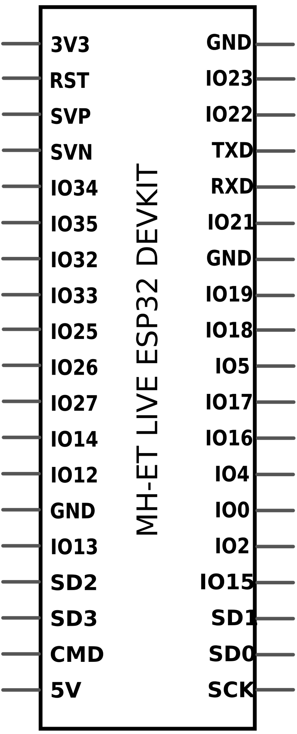
Pin Configuration and Descriptions
The MH-ET LIVE ESP32 DevKit features a total of 30 GPIO pins, which can be configured for various functions. Below is a table summarizing the key pins and their descriptions:
| Pin Name | Function(s) | Description |
|---|---|---|
| VIN | Power Input | Accepts 5V input via USB or external source. |
| 3V3 | Power Output | Provides 3.3V output for external components. |
| GND | Ground | Common ground for the circuit. |
| GPIO0 | GPIO, Boot Mode | Used for boot mode selection. |
| GPIO2 | GPIO, ADC, Touch Sensor | Multipurpose pin with ADC and touch support. |
| GPIO4 | GPIO, ADC, PWM, Touch Sensor | Multipurpose pin with PWM and touch support. |
| GPIO12 | GPIO, ADC, Touch Sensor, HSPI | Multipurpose pin with HSPI support. |
| GPIO13 | GPIO, ADC, PWM, Touch Sensor, HSPI | Multipurpose pin with PWM and HSPI support. |
| GPIO21 | GPIO, I2C SDA | Default I2C data pin. |
| GPIO22 | GPIO, I2C SCL | Default I2C clock pin. |
| EN | Enable | Resets the board when pulled low. |
For a complete pinout diagram, refer to the official datasheet.
Usage Instructions
How to Use the Component in a Circuit
Powering the Board:
- Connect the board to your computer or a USB power source using a micro-USB cable.
- Alternatively, supply 5V to the VIN pin and connect GND to the ground of your power source.
Programming the Board:
- Install the ESP32 board package in the Arduino IDE or use the ESP-IDF framework for advanced development.
- Select the correct board (
MH-ET LIVE ESP32 DevKit) and port in the Arduino IDE. - Write your code and upload it to the board via the USB connection.
Connecting Peripherals:
- Use the GPIO pins to connect sensors, actuators, or other peripherals.
- Ensure that the voltage levels of connected devices are compatible with the 3.3V logic of the ESP32.
Using Wi-Fi and Bluetooth:
- Use the built-in libraries (
WiFi.handBluetoothSerial.h) in the Arduino IDE to enable wireless communication. - Configure the network credentials or Bluetooth pairing settings in your code.
- Use the built-in libraries (
Important Considerations and Best Practices
- Voltage Levels: The GPIO pins operate at 3.3V. Avoid connecting 5V devices directly to the pins without a level shifter.
- Boot Mode: Ensure GPIO0 is not pulled low during normal operation, as this will put the board into bootloader mode.
- Power Supply: Use a stable power source to avoid unexpected resets or performance issues.
- Heat Management: The ESP32 can get warm during operation. Ensure proper ventilation if used in an enclosed space.
Example Code for Arduino UNO Integration
Below is an example of how to use the MH-ET LIVE ESP32 DevKit to read data from a DHT11 temperature and humidity sensor and send it to a serial monitor:
#include <WiFi.h> // Include Wi-Fi library for ESP32
#include <DHT.h>  // Include DHT sensor library

#define DHTPIN 4    // Define the GPIO pin connected to the DHT sensor
#define DHTTYPE DHT11 // Define the type of DHT sensor (DHT11)

DHT dht(DHTPIN, DHTTYPE); // Initialize the DHT sensor

void setup() {
  Serial.begin(115200); // Start serial communication at 115200 baud
  dht.begin();          // Initialize the DHT sensor
  Serial.println("DHT11 Sensor Example with ESP32");
}

void loop() {
  float temperature = dht.readTemperature(); // Read temperature in Celsius
  float humidity = dht.readHumidity();       // Read humidity percentage

  // Check if the readings are valid
  if (isnan(temperature) || isnan(humidity)) {
    Serial.println("Failed to read from DHT sensor!");
    return;
  }

  // Print the readings to the serial monitor
  Serial.print("Temperature: ");
  Serial.print(temperature);
  Serial.println(" °C");
  Serial.print("Humidity: ");
  Serial.print(humidity);
  Serial.println(" %");

  delay(2000); // Wait 2 seconds before the next reading
}
Troubleshooting and FAQs
Common Issues and Solutions
Board Not Detected in Arduino IDE:
- Ensure the correct USB driver is installed for the ESP32.
- Check the USB cable for data transfer capability (some cables are power-only).
- Select the correct COM port in the Arduino IDE.
Upload Fails with Timeout Error:
- Press and hold the
BOOTbutton on the board while uploading the code. - Release the button once the upload starts.
- Press and hold the
Wi-Fi Connection Fails:
- Double-check the SSID and password in your code.
- Ensure the Wi-Fi network is within range and not using unsupported security protocols.
GPIO Pin Not Working:
- Verify that the pin is not being used for another function (e.g., boot mode).
- Check for short circuits or incorrect wiring.
FAQs
Can I power the board with a battery?
Yes, you can use a 3.7V LiPo battery connected to the 3V3 pin or a 5V source connected to the VIN pin.Is the board compatible with 5V logic?
No, the GPIO pins operate at 3.3V. Use a level shifter for 5V devices.How do I reset the board?
Press theENbutton to reset the board.Can I use the board without Wi-Fi or Bluetooth?
Yes, the ESP32 can function as a standalone microcontroller for non-wireless applications.