
How to Use 9 mm Rotary Potentiometer: Examples, Pinouts, and Specs
 Design with 9 mm Rotary Potentiometer in Cirkit Designer
Introduction
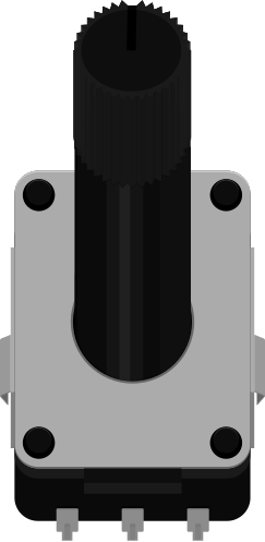
The ALPS Alpine RK09L is a 9 mm rotary potentiometer, a variable resistor designed for precise adjustment of resistance by rotating its shaft. This component is widely used in electronic circuits for applications such as volume control, brightness adjustment, and other scenarios requiring variable control. Its compact size and reliable performance make it a popular choice in consumer electronics, audio equipment, and DIY projects.
Explore Projects Built with 9 mm Rotary Potentiometer
 Open Project in Cirkit Designer
 Open Project in Cirkit Designer
 Open Project in Cirkit Designer
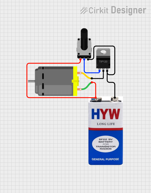 Open Project in Cirkit Designer
Explore Projects Built with 9 mm Rotary Potentiometer
Open Project in Cirkit DesignerOpen Project in Cirkit DesignerOpen Project in Cirkit DesignerOpen Project in Cirkit DesignerCommon Applications
- Volume control in audio devices
- Brightness adjustment in LED circuits
- Signal tuning in analog circuits
- User input for microcontroller-based projects
- Resistance adjustment in test and measurement equipment
Technical Specifications
The following table outlines the key technical details of the ALPS Alpine RK09L rotary potentiometer:
| Parameter | Specification |
|---|---|
| Manufacturer | ALPS Alpine |
| Part Number | RK09L |
| Resistance Range | 10 kΩ, 50 kΩ, 100 kΩ (varies by model) |
| Tolerance | ±20% |
| Power Rating | 0.05 W (50 mW) |
| Rotation Angle | 300° ± 5° |
| Shaft Length | 15 mm |
| Shaft Diameter | 6 mm |
| Operating Temperature | -10°C to +70°C |
| Mounting Style | Through-hole |
| Life Cycle | 15,000 cycles |
Pin Configuration and Descriptions
The RK09L potentiometer typically has three pins, as described below:
| Pin Number | Name | Description |
|---|---|---|
| 1 | Terminal 1 | One end of the resistive track. Connect to ground or a reference voltage. |
| 2 | Wiper | The adjustable middle pin that provides the variable resistance output. |
| 3 | Terminal 2 | The other end of the resistive track. Connect to a voltage source or reference. |
Usage Instructions
How to Use the Component in a Circuit
Basic Connection:
- Connect Terminal 1 to ground (GND).
- Connect Terminal 3 to a voltage source (e.g., 5V).
- The Wiper (Pin 2) will output a variable voltage depending on the shaft's rotation angle.
Adjusting Resistance:
- Rotate the shaft clockwise or counterclockwise to increase or decrease the resistance between the wiper and the terminals.
Microcontroller Integration:
- The potentiometer can be used as an analog input for microcontrollers like Arduino. Connect the wiper to an analog input pin to read the voltage.
Important Considerations and Best Practices
- Power Rating: Ensure the power dissipation across the potentiometer does not exceed 50 mW to avoid damage.
- Debouncing: When used in digital circuits, consider adding a capacitor across the wiper and ground to reduce noise.
- Mechanical Stress: Avoid applying excessive force to the shaft to maintain the component's longevity.
- Mounting: Secure the potentiometer firmly to the PCB to prevent mechanical instability.
Example: Using the RK09L with Arduino UNO
Below is an example of how to use the RK09L potentiometer to read analog values with an Arduino UNO:
// Example: Reading a potentiometer value with Arduino UNO
// Connect the potentiometer's wiper (Pin 2) to A0, and the other terminals to 5V and GND.

const int potPin = A0;  // Analog pin connected to the potentiometer's wiper
int potValue = 0;       // Variable to store the potentiometer reading

void setup() {
  Serial.begin(9600);  // Initialize serial communication at 9600 baud
}

void loop() {
  potValue = analogRead(potPin);  // Read the analog value from the potentiometer
  Serial.print("Potentiometer Value: ");
  Serial.println(potValue);       // Print the value to the Serial Monitor
  delay(100);                     // Small delay for stability
}
Troubleshooting and FAQs
Common Issues
No Output Voltage:
- Cause: Incorrect wiring or loose connections.
- Solution: Verify that the potentiometer is connected correctly (Pin 1 to GND, Pin 3 to VCC, Pin 2 to the output).
Inconsistent Readings:
- Cause: Noise or poor contact in the wiper.
- Solution: Add a small capacitor (e.g., 0.1 µF) between the wiper and ground to filter noise.
Potentiometer Not Responding:
- Cause: Mechanical damage or worn-out resistive track.
- Solution: Replace the potentiometer if it has exceeded its life cycle (15,000 cycles).
FAQs
Q: Can the RK09L be used for high-power applications?
A: No, the RK09L is rated for a maximum power of 50 mW. For high-power applications, consider using a higher-rated potentiometer or a digital potentiometer.
Q: How do I clean a noisy potentiometer?
A: Use a contact cleaner spray to clean the internal resistive track. Rotate the shaft several times to distribute the cleaner evenly.
Q: Can I use the RK09L for digital control?
A: The RK09L is an analog component. However, its output can be read by an ADC (Analog-to-Digital Converter) in microcontrollers for digital processing.
This concludes the documentation for the ALPS Alpine RK09L 9 mm rotary potentiometer.