
How to Use Seeed Studio XIAO ESP32S3 Plus: Examples, Pinouts, and Specs
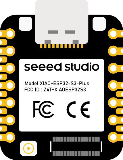
 Design with Seeed Studio XIAO ESP32S3 Plus in Cirkit Designer
Introduction
The Seeed Studio XIAO ESP32S3 Plus is a compact and powerful microcontroller board based on the ESP32-S3 chip. It is designed for IoT (Internet of Things) applications, offering built-in Wi-Fi and Bluetooth connectivity. With its small form factor, low power consumption, and high performance, this board is ideal for a wide range of projects, including smart home devices, wearable electronics, and industrial automation.
Explore Projects Built with Seeed Studio XIAO ESP32S3 Plus
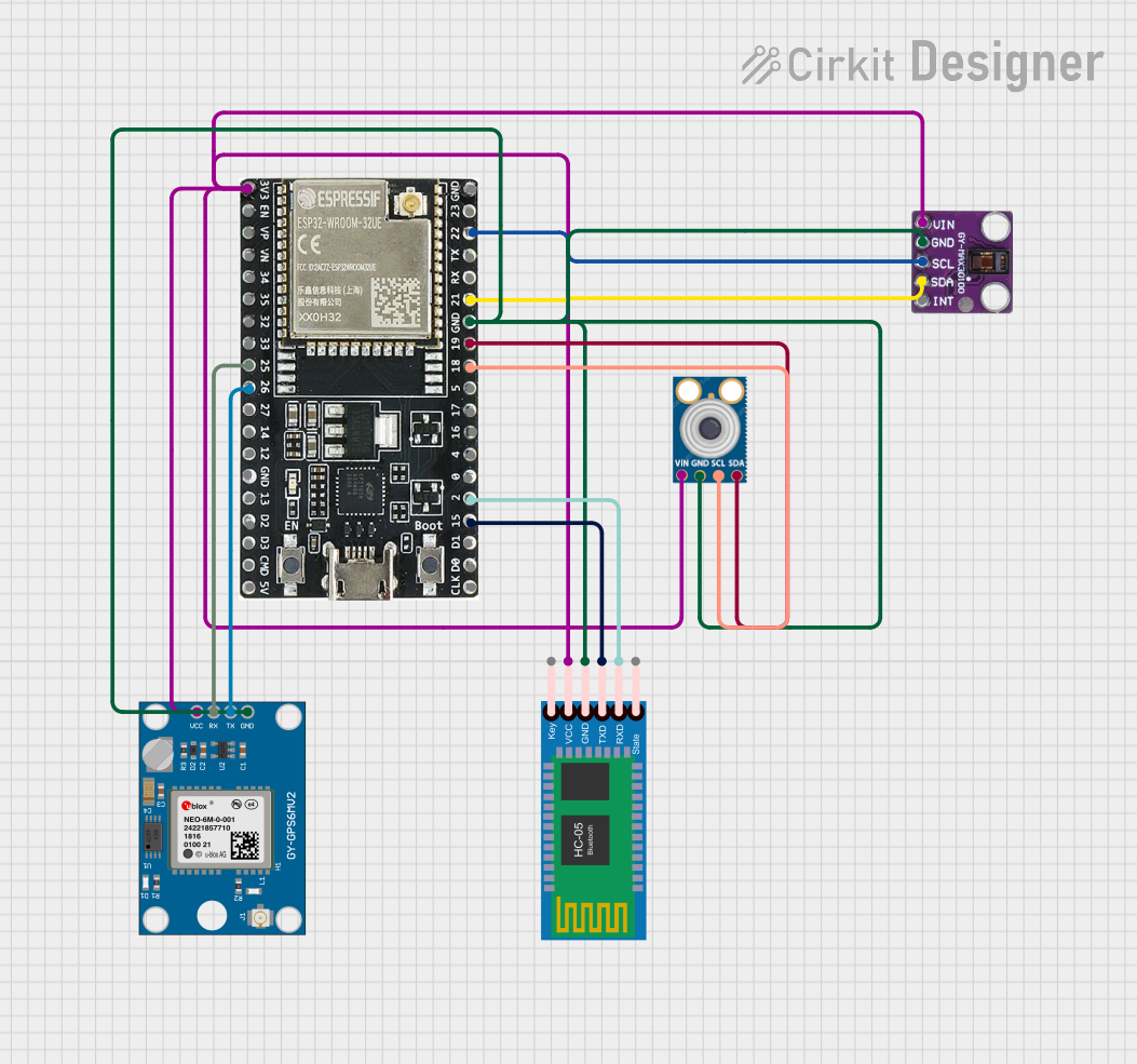 Open Project in Cirkit Designer
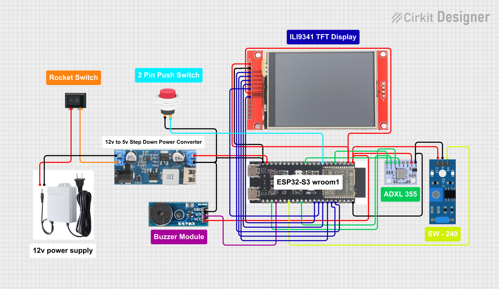 Open Project in Cirkit Designer
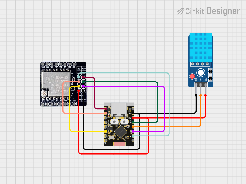 Open Project in Cirkit Designer
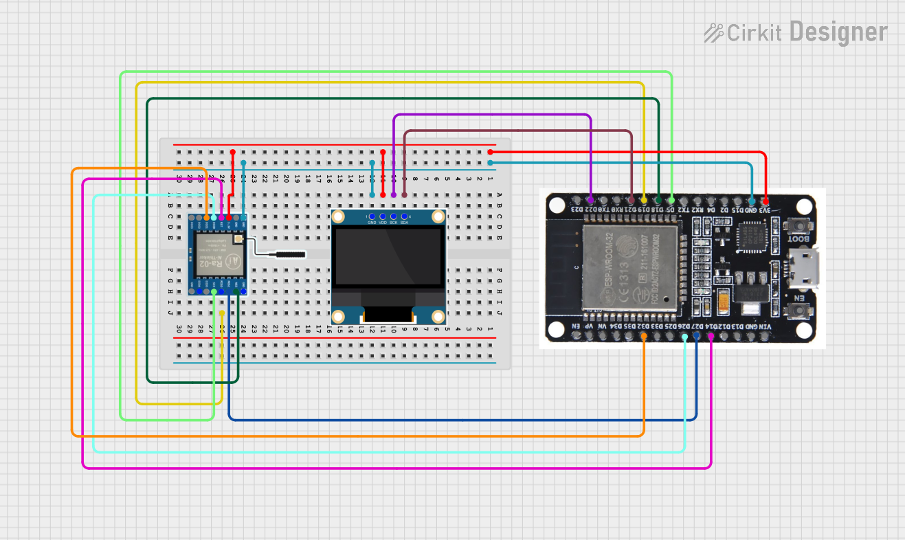 Open Project in Cirkit Designer
Explore Projects Built with Seeed Studio XIAO ESP32S3 Plus
Open Project in Cirkit DesignerOpen Project in Cirkit DesignerOpen Project in Cirkit DesignerOpen Project in Cirkit DesignerCommon Applications and Use Cases
- IoT devices and smart home automation
- Wearable electronics and fitness trackers
- Wireless data logging and monitoring
- Robotics and sensor integration
- Prototyping for AI and machine learning applications
Technical Specifications
The following table outlines the key technical details of the Seeed Studio XIAO ESP32S3 Plus:
| Specification | Details |
|---|---|
| Microcontroller | ESP32-S3 (Xtensa® 32-bit LX7 dual-core processor) |
| Clock Speed | Up to 240 MHz |
| Flash Memory | 8 MB |
| PSRAM | 8 MB |
| Wi-Fi | IEEE 802.11 b/g/n (2.4 GHz) |
| Bluetooth | Bluetooth 5.0 (LE) |
| Operating Voltage | 3.3V |
| Input Voltage | 5V (via USB-C) |
| GPIO Pins | 11 (including ADC, DAC, I2C, SPI, UART, PWM) |
| USB Interface | USB-C (supports USB OTG and programming) |
| Power Consumption | Ultra-low power consumption in deep sleep mode |
| Dimensions | 21 x 17.5 mm |
Pin Configuration and Descriptions
The Seeed Studio XIAO ESP32S3 Plus features a total of 11 GPIO pins. The table below provides details about the pin configuration:
| Pin | Name | Function | Description |
|---|---|---|---|
| 1 | 3V3 | Power | 3.3V power output |
| 2 | GND | Ground | Ground pin |
| 3 | D0 | GPIO0 / ADC / UART | General-purpose I/O, ADC, or UART |
| 4 | D1 | GPIO1 / ADC / I2C_SDA | General-purpose I/O, ADC, or I2C data line |
| 5 | D2 | GPIO2 / ADC / I2C_SCL | General-purpose I/O, ADC, or I2C clock line |
| 6 | D3 | GPIO3 / PWM | General-purpose I/O or PWM |
| 7 | D4 | GPIO4 / SPI_MOSI | General-purpose I/O or SPI MOSI |
| 8 | D5 | GPIO5 / SPI_MISO | General-purpose I/O or SPI MISO |
| 9 | D6 | GPIO6 / SPI_SCK | General-purpose I/O or SPI clock |
| 10 | D7 | GPIO7 / UART_TX | General-purpose I/O or UART transmit |
| 11 | D8 | GPIO8 / UART_RX | General-purpose I/O or UART receive |
Usage Instructions
How to Use the Component in a Circuit
- Powering the Board: Connect the board to a 5V power source using the USB-C port. The onboard voltage regulator will step down the voltage to 3.3V.
- Programming: Use the Arduino IDE or other compatible development environments to program the board. Select "ESP32-S3" as the board type in the IDE.
- Connecting Peripherals: Use the GPIO pins to connect sensors, actuators, or other peripherals. Ensure that the voltage levels of connected devices are compatible with the 3.3V logic level of the board.
- Wi-Fi and Bluetooth: Utilize the built-in Wi-Fi and Bluetooth capabilities for wireless communication. Libraries such as
WiFi.handBluetoothSerial.hcan be used for development.
Important Considerations and Best Practices
- Voltage Levels: Ensure that all connected peripherals operate at 3.3V logic levels to avoid damaging the board.
- Deep Sleep Mode: Use the deep sleep mode to minimize power consumption in battery-powered applications.
- Heat Management: Although the board is efficient, prolonged high-performance operation may generate heat. Ensure proper ventilation if used in enclosed spaces.
- Firmware Updates: Regularly update the firmware to ensure compatibility with the latest libraries and features.
Example Code for Arduino UNO Integration
Below is an example of how to use the Seeed Studio XIAO ESP32S3 Plus to connect to a Wi-Fi network and send data to a server:
#include <WiFi.h>

// Replace with your network credentials
const char* ssid = "Your_SSID";
const char* password = "Your_PASSWORD";

void setup() {
  Serial.begin(115200); // Initialize serial communication at 115200 baud
  WiFi.begin(ssid, password); // Connect to Wi-Fi network

  Serial.print("Connecting to Wi-Fi");
  while (WiFi.status() != WL_CONNECTED) {
    delay(500);
    Serial.print("."); // Print dots while connecting
  }
  Serial.println("\nConnected to Wi-Fi");
  Serial.print("IP Address: ");
  Serial.println(WiFi.localIP()); // Print the device's IP address
}

void loop() {
  // Add your main code here
}
Troubleshooting and FAQs
Common Issues Users Might Face
Board Not Detected by IDE:
- Ensure that the correct board type ("ESP32-S3") is selected in the Arduino IDE.
- Install the latest ESP32 board package in the Arduino IDE via the Board Manager.
- Check the USB cable and port for proper connection.
Wi-Fi Connection Fails:
- Verify the SSID and password for the Wi-Fi network.
- Ensure that the Wi-Fi network operates on the 2.4 GHz band (not 5 GHz).
Peripherals Not Responding:
- Double-check the wiring and pin assignments in your code.
- Ensure that the connected peripherals are compatible with 3.3V logic levels.
Solutions and Tips for Troubleshooting
- Reset the Board: Press the reset button on the board to restart it if it becomes unresponsive.
- Check Power Supply: Ensure that the board is receiving sufficient power (5V via USB-C).
- Debugging: Use the Serial Monitor in the Arduino IDE to debug your code and monitor outputs.
- Consult Documentation: Refer to the official Seeed Studio documentation and forums for additional support.
By following this documentation, you can effectively utilize the Seeed Studio XIAO ESP32S3 Plus for your IoT and embedded system projects.