
How to Use JOYSTICK_MINI: Examples, Pinouts, and Specs
 Design with JOYSTICK_MINI in Cirkit Designer
Introduction
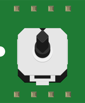
The JOYSTICK_MINI is a compact input device designed for directional control and movement detection. It features a pivoting stick that allows users to interact with systems by detecting movement in multiple directions. This component is widely used in applications such as gaming controllers, robotics, remote-controlled devices, and other interactive systems requiring precise directional input.
Explore Projects Built with JOYSTICK_MINI
 Open Project in Cirkit Designer
 Open Project in Cirkit Designer
 Open Project in Cirkit Designer
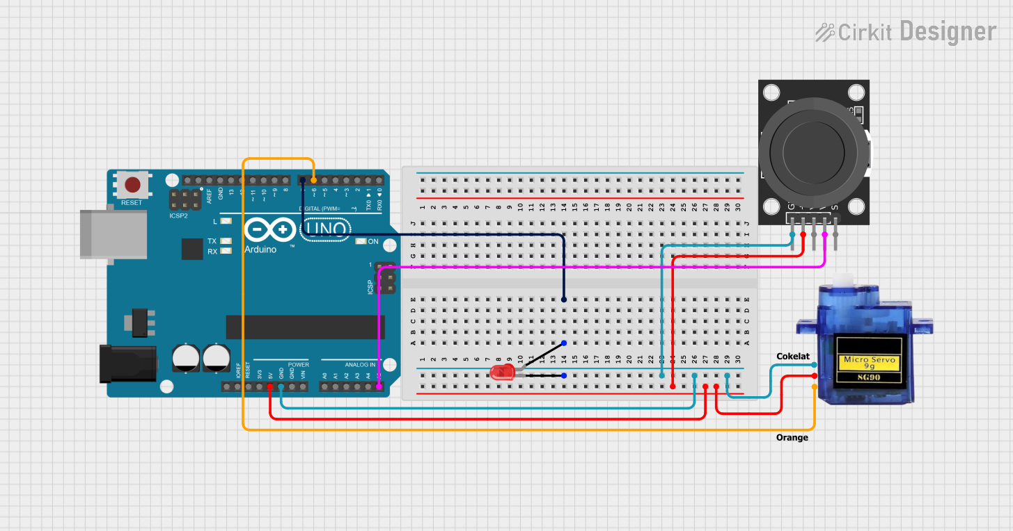 Open Project in Cirkit Designer
Explore Projects Built with JOYSTICK_MINI
Open Project in Cirkit DesignerOpen Project in Cirkit DesignerOpen Project in Cirkit DesignerOpen Project in Cirkit DesignerCommon Applications:
- Gaming controllers for directional navigation
- Robotic control systems
- Remote-controlled vehicles and drones
- User interface navigation in embedded systems
- DIY electronics and Arduino projects
Technical Specifications
Key Technical Details:
- Operating Voltage: 3.3V to 5V
- Output Type: Analog (X and Y axes), Digital (button press)
- X-Axis and Y-Axis Range: 0V to Vcc (typically 0V to 5V)
- Button Type: Momentary push-button (active LOW)
- Dimensions: 26mm x 32mm x 20mm (approx.)
- Mounting Type: PCB mount with solderable pins
Pin Configuration and Descriptions:
The JOYSTICK_MINI typically has 5 pins. The table below describes each pin:
| Pin | Name | Description |
|---|---|---|
| 1 | GND | Ground connection for the joystick. |
| 2 | VCC | Power supply input (3.3V to 5V). |
| 3 | VRx | Analog output for the X-axis movement. Voltage varies based on joystick position. |
| 4 | VRy | Analog output for the Y-axis movement. Voltage varies based on joystick position. |
| 5 | SW | Digital output for the push-button. Active LOW when pressed. |
Usage Instructions
How to Use the JOYSTICK_MINI in a Circuit:
Powering the Joystick:
- Connect the VCC pin to a 3.3V or 5V power source.
- Connect the GND pin to the ground of your circuit.
Reading X and Y Axis Values:
- Connect the VRx and VRy pins to the analog input pins of a microcontroller (e.g., Arduino).
- The voltage on these pins will vary between 0V and Vcc depending on the joystick's position:
- Center position: ~Vcc/2
- Full left or down: ~0V
- Full right or up: ~Vcc
Using the Push-Button:
- Connect the SW pin to a digital input pin of your microcontroller.
- Use a pull-up resistor (if not already included on the joystick module) to ensure the pin reads HIGH when the button is not pressed.
- When the button is pressed, the SW pin will output LOW.
Example Arduino UNO Code:
The following code demonstrates how to read the X and Y axis values and detect button presses using an Arduino UNO.
// Define pin connections for the joystick
const int VRxPin = A0; // X-axis connected to analog pin A0
const int VRyPin = A1; // Y-axis connected to analog pin A1
const int SWPin = 2;   // Push-button connected to digital pin 2

void setup() {
  // Initialize serial communication for debugging
  Serial.begin(9600);

  // Configure the push-button pin as input with internal pull-up resistor
  pinMode(SWPin, INPUT_PULLUP);
}

void loop() {
  // Read the X and Y axis values (0 to 1023 for 10-bit ADC)
  int xValue = analogRead(VRxPin);
  int yValue = analogRead(VRyPin);

  // Read the state of the push-button (LOW when pressed)
  bool buttonPressed = !digitalRead(SWPin);

  // Print the joystick values to the Serial Monitor
  Serial.print("X: ");
  Serial.print(xValue);
  Serial.print(" | Y: ");
  Serial.print(yValue);
  Serial.print(" | Button: ");
  Serial.println(buttonPressed ? "Pressed" : "Released");

  // Add a small delay for stability
  delay(100);
}
Important Considerations and Best Practices:
- Voltage Compatibility: Ensure the joystick's operating voltage matches your microcontroller's input voltage (e.g., 5V for Arduino UNO).
- Debouncing the Button: If the push-button is used in critical applications, consider implementing software debouncing to avoid false triggers.
- Calibration: For precise applications, calibrate the joystick to account for any offset in the center position.
- Mechanical Stress: Avoid applying excessive force to the joystick to prevent damage to the internal components.
Troubleshooting and FAQs
Common Issues and Solutions:
No Output from X or Y Axis:
- Cause: Incorrect wiring or loose connections.
- Solution: Verify that the VRx and VRy pins are properly connected to the microcontroller's analog input pins.
Button Not Responding:
- Cause: Missing pull-up resistor or incorrect pin configuration.
- Solution: Use the internal pull-up resistor by configuring the pin as
INPUT_PULLUPin your code.
Inconsistent or Noisy Readings:
- Cause: Electrical noise or poor power supply.
- Solution: Add decoupling capacitors (e.g., 0.1µF) between VCC and GND near the joystick module.
Joystick Not Centered:
- Cause: Manufacturing tolerances or wear and tear.
- Solution: Implement software calibration to adjust for any offset in the center position.
FAQs:
Q: Can the JOYSTICK_MINI be used with a Raspberry Pi?
A: Yes, the joystick can be used with a Raspberry Pi. However, since the Raspberry Pi lacks analog input pins, you will need an external ADC (Analog-to-Digital Converter) module to read the X and Y axis values.
Q: What is the lifespan of the joystick?
A: The lifespan depends on usage and environmental conditions. Under normal use, the joystick can last for thousands of cycles.
Q: Can I use the joystick for 360-degree control?
A: Yes, the joystick provides analog outputs for both X and Y axes, allowing for smooth 360-degree directional control.
Q: Is the push-button necessary for operation?
A: No, the push-button is optional and can be left unconnected if not required for your application.