How to Use STM32H7xx: Examples, Pinouts, and Specs
Introduction
The STM32H7xx series, manufactured by DEVEBOX, is a family of high-performance microcontrollers based on the ARM Cortex-M7 core. These microcontrollers are designed for applications requiring exceptional processing power, advanced peripherals, and low power consumption. The STM32H7xx series is ideal for demanding applications such as industrial automation, motor control, IoT devices, audio processing, and advanced graphics.
Explore Projects Built with STM32H7xx
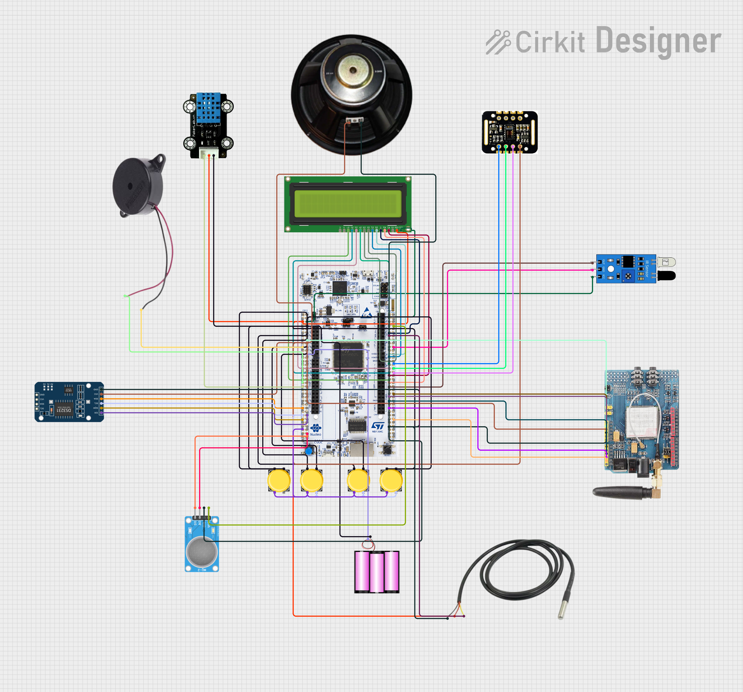

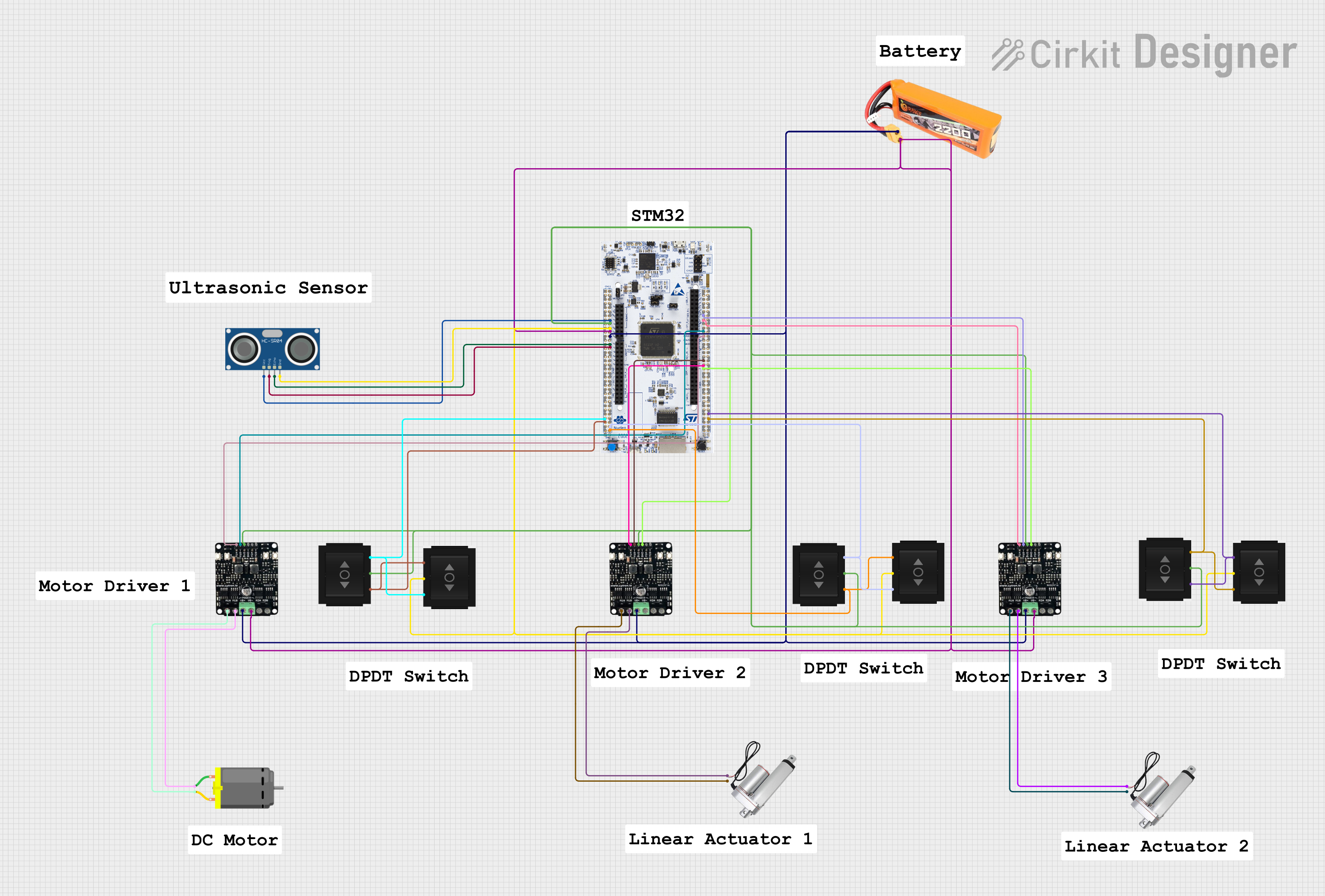

Explore Projects Built with STM32H7xx
Common Applications and Use Cases
- Industrial automation and control systems
- High-performance motor control
- IoT devices and edge computing
- Audio and video processing
- Advanced graphical user interfaces (GUIs)
- Medical devices and instrumentation
- Robotics and drones
Technical Specifications
The STM32H7xx series offers a wide range of features and configurations. Below are the key technical specifications:
General Specifications
- Core: ARM Cortex-M7, up to 480 MHz
- Flash Memory: Up to 2 MB
- RAM: Up to 1 MB (including TCM RAM)
- Operating Voltage: 1.62V to 3.6V
- I/O Pins: Up to 168 GPIOs
- Communication Interfaces: UART, SPI, I2C, CAN, USB, Ethernet
- Timers: Advanced timers, general-purpose timers, and low-power timers
- ADC/DAC: 16-bit ADC, 12-bit DAC
- Power Modes: Sleep, Stop, Standby, and VBAT modes for low power consumption
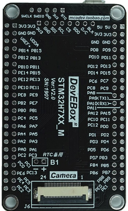
Pin Configuration and Descriptions
The STM32H7xx microcontrollers are available in various packages, such as LQFP, BGA, and WLCSP. Below is an example pinout for the STM32H743 in an LQFP144 package:
| Pin Number | Pin Name | Function | Description |
|---|---|---|---|
| 1 | VDD | Power Supply | Positive power supply (3.3V) |
| 2 | VSS | Ground | Ground connection |
| 3 | PA0 | GPIO/ADC_IN0/USART2_CTS | General-purpose I/O or ADC input |
| 4 | PA1 | GPIO/ADC_IN1/USART2_RTS | General-purpose I/O or ADC input |
| 5 | PB6 | GPIO/I2C1_SCL/USART1_TX | I2C clock line or UART TX |
| 6 | PB7 | GPIO/I2C1_SDA/USART1_RX | I2C data line or UART RX |
| ... | ... | ... | ... |
| 144 | NRST | Reset | Active-low reset pin |
Refer to the specific datasheet for the exact pinout of your STM32H7xx variant.
Usage Instructions
How to Use the STM32H7xx in a Circuit
- Power Supply: Connect the VDD pins to a 3.3V power source and the VSS pins to ground. Ensure proper decoupling capacitors are placed near the power pins.
- Clock Configuration: Use an external crystal oscillator or the internal RC oscillator for the system clock. Configure the clock settings in the firmware.
- Programming: Use an ST-LINK programmer/debugger to upload firmware via the SWD (Serial Wire Debug) interface.
- Peripherals: Connect peripherals (e.g., sensors, displays, communication modules) to the appropriate GPIO pins. Configure the pins in the firmware for the desired function (e.g., UART, SPI, I2C).
- Boot Mode: Set the BOOT pins to select the boot mode (e.g., boot from Flash, RAM, or system memory).
Important Considerations and Best Practices
- Power Supply Decoupling: Place decoupling capacitors (e.g., 0.1 µF) close to the VDD pins to reduce noise.
- Clock Stability: Use a stable external crystal oscillator for applications requiring precise timing.
- Debugging: Always enable the SWD interface for debugging and troubleshooting.
- Low Power Modes: Utilize the low-power modes (Sleep, Stop, Standby) to reduce power consumption in battery-powered applications.
- Firmware Development: Use the STM32CubeIDE or Keil MDK for firmware development. The STM32CubeMX tool can help with peripheral configuration and code generation.
Example Code for Arduino UNO Integration
Although the STM32H7xx is not directly compatible with Arduino UNO, it can communicate with an Arduino via UART. Below is an example of Arduino code to send data to the STM32H7xx:
// Arduino UNO code to send data via UART to STM32H7xx

void setup() {
  Serial.begin(9600); // Initialize UART at 9600 baud rate
}

void loop() {
  Serial.println("Hello, STM32H7xx!"); // Send data to STM32H7xx
  delay(1000); // Wait for 1 second
}
On the STM32H7xx side, configure the UART peripheral to receive data from the Arduino.
Troubleshooting and FAQs
Common Issues and Solutions
Microcontroller Not Powering On
- Cause: Incorrect power supply or missing decoupling capacitors.
- Solution: Verify the power supply voltage (3.3V) and ensure proper decoupling capacitors are in place.
Unable to Program the Microcontroller
- Cause: Incorrect BOOT pin configuration or faulty ST-LINK connection.
- Solution: Check the BOOT pin settings and ensure the ST-LINK is properly connected.
Peripheral Not Working
- Cause: Incorrect pin configuration or clock settings.
- Solution: Verify the pin configuration and ensure the peripheral clock is enabled in the firmware.
High Power Consumption
- Cause: Unused peripherals or incorrect power mode.
- Solution: Disable unused peripherals and use low-power modes when possible.
FAQs
Q: Can I use the STM32H7xx with 5V logic devices?
A: No, the STM32H7xx operates at 3.3V logic levels. Use level shifters to interface with 5V devices.
Q: What development tools are recommended for STM32H7xx?
A: Use STM32CubeIDE, STM32CubeMX, or Keil MDK for development. These tools provide comprehensive support for STM32 microcontrollers.
Q: How do I update the firmware on the STM32H7xx?
A: Use the ST-LINK programmer or the built-in bootloader (via UART, USB, or CAN) to update the firmware.
Q: Can I use the STM32H7xx for real-time applications?
A: Yes, the ARM Cortex-M7 core with its high clock speed and advanced features is well-suited for real-time applications.