
How to Use LITTLEBITS_MALE: Examples, Pinouts, and Specs
 Design with LITTLEBITS_MALE in Cirkit Designer
Introduction
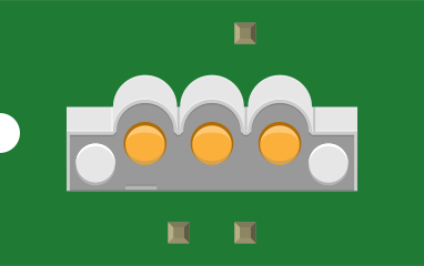
The LITTLEBITS_MALE is a modular electronic building block manufactured by littleBits. It is designed to simplify prototyping and experimentation by providing a plug-and-play interface for connecting to other littleBits components. The male connectors on this module allow seamless integration with other littleBits modules, making it ideal for rapid prototyping, educational projects, and creative electronics applications.
Explore Projects Built with LITTLEBITS_MALE
 Open Project in Cirkit Designer
 Open Project in Cirkit Designer
 Open Project in Cirkit Designer
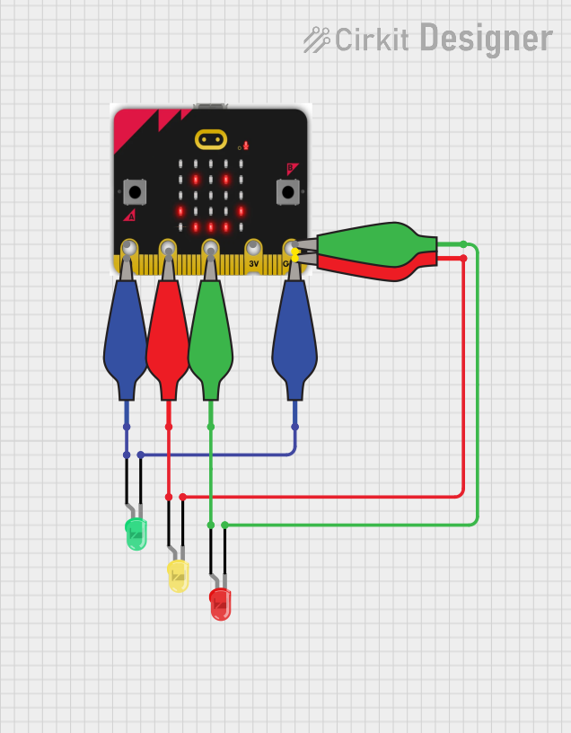 Open Project in Cirkit Designer
Explore Projects Built with LITTLEBITS_MALE
Open Project in Cirkit DesignerOpen Project in Cirkit DesignerOpen Project in Cirkit DesignerOpen Project in Cirkit DesignerCommon Applications and Use Cases
- Rapid prototyping of electronic circuits
- Educational tools for teaching electronics and programming
- DIY projects and maker activities
- Integration with other littleBits modules for creating interactive systems
Technical Specifications
Key Technical Details
- Manufacturer: littleBits
- Connector Type: Male
- Operating Voltage: 5V DC (compatible with littleBits power modules)
- Current Rating: Up to 1A
- Dimensions: 20mm x 20mm x 10mm
- Weight: 5g
- Material: Durable plastic housing with gold-plated connectors for reliable connections
Pin Configuration and Descriptions
The LITTLEBITS_MALE module features a single male connector with the following pinout:
| Pin | Name | Description |
|---|---|---|
| 1 | VCC | Supplies 5V DC power to connected modules. |
| 2 | GND | Ground connection for completing the circuit. |
| 3 | Signal (SIG) | Transmits data or control signals between modules. |
Usage Instructions
How to Use the LITTLEBITS_MALE in a Circuit
Connect to a Power Module:
Begin by connecting the LITTLEBITS_MALE module to a littleBits power module (e.g., a battery-powered module). Ensure the male connector is securely attached to the female connector of the power module.Attach Additional Modules:
Use the male connector to link the LITTLEBITS_MALE module to other littleBits modules, such as sensors, LEDs, or motors. The modular design ensures a secure and reliable connection.Integrate with External Systems:
The LITTLEBITS_MALE module can also be used to interface with external systems, such as microcontrollers (e.g., Arduino UNO). Use jumper wires to connect the male pins to the corresponding pins on the external system.
Important Considerations and Best Practices
- Polarity: Always ensure the correct orientation of the male connector when attaching it to other modules. Incorrect connections may damage the components.
- Power Supply: Use only littleBits-compatible power modules to avoid overvoltage or undervoltage issues.
- Signal Integrity: When transmitting data or control signals, ensure the connections are secure to prevent signal loss or interference.
- Handling: Avoid applying excessive force when connecting or disconnecting modules to prevent damage to the connectors.
Example: Connecting to an Arduino UNO
The LITTLEBITS_MALE module can be used to interface with an Arduino UNO for custom projects. Below is an example of how to connect and program the module:
Wiring Diagram
- Connect the VCC pin of the LITTLEBITS_MALE to the 5V pin on the Arduino UNO.
- Connect the GND pin of the LITTLEBITS_MALE to the GND pin on the Arduino UNO.
- Connect the Signal (SIG) pin of the LITTLEBITS_MALE to a digital pin (e.g., D2) on the Arduino UNO.
Arduino Code Example
// Example code for using the LITTLEBITS_MALE module with an Arduino UNO
// This code reads a signal from the LITTLEBITS_MALE module and toggles an LED

const int signalPin = 2; // Pin connected to the SIG pin of LITTLEBITS_MALE
const int ledPin = 13;   // Built-in LED on Arduino UNO

void setup() {
  pinMode(signalPin, INPUT); // Set the signal pin as input
  pinMode(ledPin, OUTPUT);   // Set the LED pin as output
  Serial.begin(9600);        // Initialize serial communication for debugging
}

void loop() {
  int signalState = digitalRead(signalPin); // Read the signal state

  if (signalState == HIGH) {
    digitalWrite(ledPin, HIGH); // Turn on the LED if signal is HIGH
    Serial.println("Signal HIGH: LED ON");
  } else {
    digitalWrite(ledPin, LOW);  // Turn off the LED if signal is LOW
    Serial.println("Signal LOW: LED OFF");
  }

  delay(100); // Small delay for stability
}
Troubleshooting and FAQs
Common Issues and Solutions
Module Not Powering On
- Cause: The LITTLEBITS_MALE module is not properly connected to a power module.
- Solution: Ensure the male connector is securely attached to a powered littleBits module.
Signal Not Detected
- Cause: Loose or incorrect connections between the LITTLEBITS_MALE module and other components.
- Solution: Double-check all connections and ensure the signal pin is properly wired.
Intermittent Connections
- Cause: Dust or debris on the connectors.
- Solution: Clean the connectors with a soft, dry cloth to ensure a reliable connection.
Overheating
- Cause: Excessive current draw or incorrect power supply.
- Solution: Verify that the connected modules do not exceed the 1A current rating and use only littleBits-compatible power sources.
FAQs
Q1: Can the LITTLEBITS_MALE module be used with non-littleBits components?
A1: Yes, the LITTLEBITS_MALE module can interface with non-littleBits components, such as microcontrollers, using jumper wires. Ensure proper pin mapping and voltage compatibility.
Q2: What is the maximum number of modules that can be connected to the LITTLEBITS_MALE?
A2: The number of modules depends on the power supply and the current requirements of each module. Ensure the total current draw does not exceed 1A.
Q3: Is the LITTLEBITS_MALE module compatible with 3.3V systems?
A3: The module is designed for 5V systems. Using it with 3.3V systems may result in unreliable operation or signal issues.
Q4: How durable is the LITTLEBITS_MALE module?
A4: The module is built with durable plastic housing and gold-plated connectors, ensuring long-lasting performance with proper handling.