
How to Use FPC Breakout board 14p: Examples, Pinouts, and Specs
 Design with FPC Breakout board 14p in Cirkit Designer
Introduction
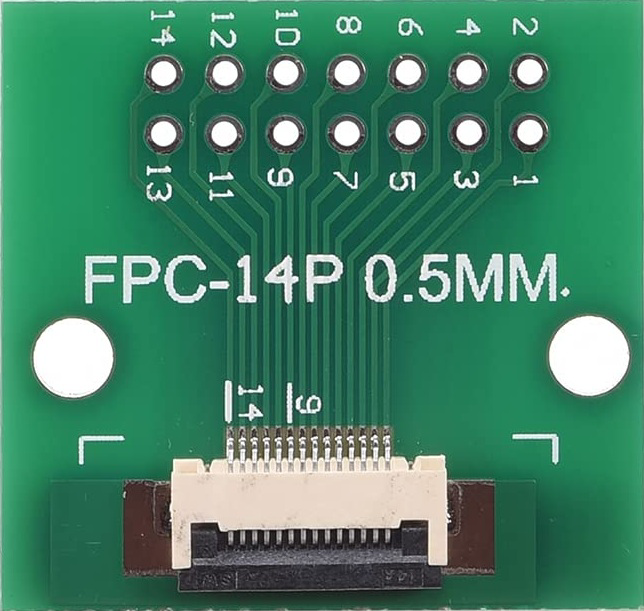
The FPC Breakout Board 14p is a versatile adapter designed to connect flexible printed circuit (FPC) cables to standard pin headers. This breakout board features 14 pins, making it ideal for interfacing FPC cables with breadboards, microcontrollers, or other prototyping tools. It simplifies the process of testing and prototyping circuits that use FPC cables, which are commonly found in displays, sensors, and other compact electronic devices.
Explore Projects Built with FPC Breakout board 14p
 Open Project in Cirkit Designer
 Open Project in Cirkit Designer
 Open Project in Cirkit Designer
 Open Project in Cirkit Designer
Explore Projects Built with FPC Breakout board 14p
Open Project in Cirkit DesignerOpen Project in Cirkit DesignerOpen Project in Cirkit DesignerOpen Project in Cirkit DesignerCommon Applications and Use Cases
- Prototyping circuits with FPC cables
- Interfacing FPC-based displays or sensors with microcontrollers
- Testing and debugging FPC-connected devices
- Creating custom connections for compact electronic designs
Technical Specifications
- Number of Pins: 14
- Connector Type: FPC ZIF (Zero Insertion Force) connector
- Pin Pitch: 0.5 mm
- Output Interface: Standard 2.54 mm (0.1 inch) pin headers
- Board Dimensions: Approximately 25 mm x 20 mm
- Material: FR4 PCB with gold-plated contacts
- Operating Voltage: Compatible with 3.3V and 5V systems
- Compatibility: Supports 14-pin FPC cables with 0.5 mm pitch
Pin Configuration and Descriptions
The FPC Breakout Board 14p maps the 14 pins of the FPC connector to standard pin headers. Below is the pin configuration:
| Pin Number | FPC Connector Pin | Header Pin | Description |
|---|---|---|---|
| 1 | 1 | 1 | Signal or power line |
| 2 | 2 | 2 | Signal or power line |
| 3 | 3 | 3 | Signal or power line |
| 4 | 4 | 4 | Signal or power line |
| 5 | 5 | 5 | Signal or power line |
| 6 | 6 | 6 | Signal or power line |
| 7 | 7 | 7 | Signal or power line |
| 8 | 8 | 8 | Signal or power line |
| 9 | 9 | 9 | Signal or power line |
| 10 | 10 | 10 | Signal or power line |
| 11 | 11 | 11 | Signal or power line |
| 12 | 12 | 12 | Signal or power line |
| 13 | 13 | 13 | Signal or power line |
| 14 | 14 | 14 | Signal or power line |
Note: The specific function of each pin depends on the FPC cable and the connected device. Refer to the datasheet of the FPC cable or device for detailed pin assignments.
Usage Instructions
How to Use the FPC Breakout Board in a Circuit
Insert the FPC Cable:
- Open the ZIF connector latch by gently lifting it.
- Insert the FPC cable into the connector, ensuring the contacts are aligned.
- Close the latch to secure the cable in place.
Connect to a Breadboard or Microcontroller:
- Use the 2.54 mm pin headers to connect the breakout board to a breadboard or directly to a microcontroller.
- Ensure proper alignment of the pins to avoid incorrect connections.
Power the Circuit:
- Provide the appropriate voltage (3.3V or 5V) to the connected device, as specified in its datasheet.
Test and Debug:
- Use a multimeter or oscilloscope to verify connections and signals as needed.
Important Considerations and Best Practices
- Handle with Care: FPC cables are delicate and can be damaged if bent excessively or inserted improperly.
- Check Pin Assignments: Always verify the pin assignments of the FPC cable and the breakout board before powering the circuit.
- Avoid Overvoltage: Ensure the connected device operates within the specified voltage range to prevent damage.
- Secure Connections: Ensure the FPC cable is firmly secured in the ZIF connector to avoid intermittent connections.
Example: Connecting to an Arduino UNO
Below is an example of how to connect the FPC Breakout Board 14p to an Arduino UNO for reading data from an FPC-based sensor.
// Example code for interfacing an FPC-based sensor with Arduino UNO
// Ensure the FPC cable is properly connected to the breakout board

const int sensorPin = A0; // Define the analog pin connected to the sensor
int sensorValue = 0;      // Variable to store the sensor reading

void setup() {
  Serial.begin(9600); // Initialize serial communication at 9600 baud
  pinMode(sensorPin, INPUT); // Set the sensor pin as input
}

void loop() {
  sensorValue = analogRead(sensorPin); // Read the sensor value
  Serial.print("Sensor Value: ");      // Print the sensor value to the serial monitor
  Serial.println(sensorValue);
  delay(500); // Wait for 500 ms before the next reading
}
Note: Modify the pin assignments and code logic based on the specific FPC device being used.
Troubleshooting and FAQs
Common Issues and Solutions
FPC Cable Not Detected:
- Cause: Improper insertion of the FPC cable into the ZIF connector.
- Solution: Reinsert the cable, ensuring proper alignment and secure the latch.
Intermittent Connections:
- Cause: Loose connections between the breakout board and the breadboard or microcontroller.
- Solution: Check and secure all connections. Use jumper wires or solder the headers if necessary.
No Signal or Incorrect Readings:
- Cause: Incorrect pin assignments or voltage mismatch.
- Solution: Verify the pin assignments and ensure the voltage matches the device's requirements.
Damaged FPC Cable:
- Cause: Excessive bending or improper handling of the FPC cable.
- Solution: Replace the damaged cable and handle future cables with care.
FAQs
Q: Can this breakout board be used with FPC cables of different pin counts?
A: No, this breakout board is specifically designed for 14-pin FPC cables with a 0.5 mm pitch.
Q: Is the breakout board compatible with 1.8V systems?
A: The breakout board itself does not regulate voltage. Ensure the connected device supports 1.8V operation.
Q: Can I solder the FPC cable directly to the breakout board?
A: It is not recommended to solder FPC cables directly, as they are designed for use with ZIF connectors.
Q: How do I identify the pin 1 orientation on the FPC connector?
A: Pin 1 is typically marked on the PCB silkscreen or indicated by a small triangle or dot near the connector.
By following this documentation, you can effectively use the FPC Breakout Board 14p for your prototyping and testing needs.