
How to Use HW-131: Examples, Pinouts, and Specs
 Design with HW-131 in Cirkit Designer
Introduction
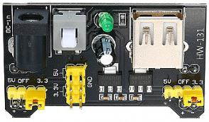
The HW-131 is a versatile electronic component widely used in signal processing and control systems. Its compact design makes it ideal for integration into both consumer and industrial devices. The HW-131 is known for its reliability and ease of use, making it a popular choice for engineers and hobbyists alike.
Explore Projects Built with HW-131
 Open Project in Cirkit Designer
 Open Project in Cirkit Designer
 Open Project in Cirkit Designer
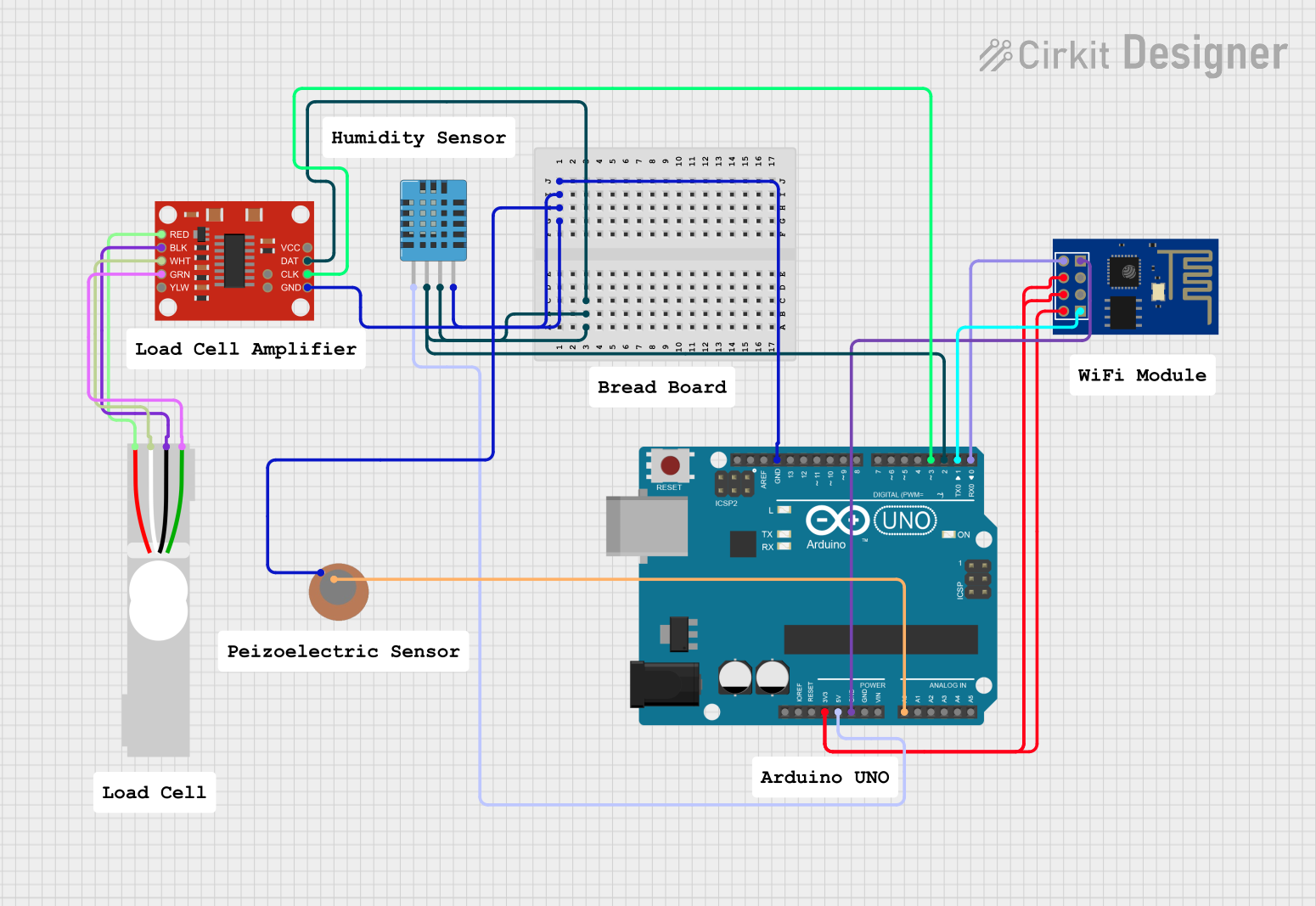 Open Project in Cirkit Designer
Explore Projects Built with HW-131
Open Project in Cirkit DesignerOpen Project in Cirkit DesignerOpen Project in Cirkit DesignerOpen Project in Cirkit DesignerCommon Applications and Use Cases
- Signal amplification and conditioning
- Control systems in industrial automation
- Consumer electronics, such as audio devices
- Prototyping and educational projects
- Integration into microcontroller-based systems
Technical Specifications
The HW-131 is designed to operate efficiently in a variety of environments. Below are its key technical details:
General Specifications
| Parameter | Value |
|---|---|
| Operating Voltage | 3.3V to 5V |
| Operating Current | 10mA (typical) |
| Signal Input Range | 0V to 5V |
| Output Signal Range | 0V to 5V |
| Operating Temperature | -20°C to 85°C |
| Dimensions | 25mm x 15mm x 5mm |
Pin Configuration and Descriptions
The HW-131 typically features a 4-pin interface. Below is the pinout and description:
| Pin Number | Pin Name | Description |
|---|---|---|
| 1 | VCC | Power supply input (3.3V to 5V) |
| 2 | GND | Ground connection |
| 3 | IN | Signal input pin |
| 4 | OUT | Signal output pin |
Usage Instructions
The HW-131 is straightforward to use in a variety of circuits. Below are the steps and considerations for integrating it into your project:
How to Use the HW-131 in a Circuit
- Power the HW-131: Connect the
VCCpin to a 3.3V or 5V power source and theGNDpin to the ground of your circuit. - Input Signal: Feed the signal you want to process into the
INpin. Ensure the input voltage does not exceed the specified range (0V to 5V). - Output Signal: The processed signal will be available at the
OUTpin. Connect this pin to the next stage of your circuit (e.g., a microcontroller or another processing module).
Important Considerations and Best Practices
- Power Supply: Ensure a stable power supply to avoid noise or instability in the output signal.
- Signal Range: Do not exceed the input signal range of 0V to 5V to prevent damage to the component.
- Decoupling Capacitor: Place a decoupling capacitor (e.g., 0.1µF) between
VCCandGNDto filter out power supply noise. - Mounting: Secure the HW-131 on a PCB or breadboard to prevent loose connections.
Example: Connecting HW-131 to an Arduino UNO
The HW-131 can be easily interfaced with an Arduino UNO for signal processing. Below is an example setup and code:
Circuit Connections
- Connect the
VCCpin of the HW-131 to the 5V pin of the Arduino. - Connect the
GNDpin of the HW-131 to the GND pin of the Arduino. - Connect the
INpin of the HW-131 to an analog signal source. - Connect the
OUTpin of the HW-131 to an analog input pin on the Arduino (e.g., A0).
Arduino Code
// Example code for reading the output of HW-131 using Arduino UNO

const int hw131OutputPin = A0; // HW-131 OUT pin connected to Arduino A0

void setup() {
  Serial.begin(9600); // Initialize serial communication at 9600 baud
}

void loop() {
  int sensorValue = analogRead(hw131OutputPin); // Read the analog value from HW-131
  float voltage = sensorValue * (5.0 / 1023.0); // Convert the reading to voltage

  // Print the voltage to the Serial Monitor
  Serial.print("HW-131 Output Voltage: ");
  Serial.print(voltage);
  Serial.println(" V");

  delay(500); // Wait for 500ms before the next reading
}
Troubleshooting and FAQs
Common Issues and Solutions
No Output Signal
- Cause: Incorrect wiring or loose connections.
- Solution: Double-check all connections, ensuring the
VCCandGNDpins are properly connected.
Output Signal is Noisy
- Cause: Unstable power supply or external interference.
- Solution: Add a decoupling capacitor between
VCCandGND. Ensure the power supply is stable.
Component Overheating
- Cause: Exceeding the input voltage or current limits.
- Solution: Verify that the input signal and power supply are within the specified ranges.
Arduino Reads Incorrect Values
- Cause: Incorrect analog reference or improper scaling in the code.
- Solution: Ensure the Arduino is using the correct analog reference (default is 5V). Check the scaling factor in the code.
FAQs
Q1: Can the HW-131 handle AC signals?
A1: The HW-131 is designed for DC signals. If you need to process AC signals, consider using a rectifier circuit to convert AC to DC before feeding it into the HW-131.
Q2: What is the maximum input frequency the HW-131 can handle?
A2: The maximum input frequency depends on the specific application and circuit design. For most use cases, it can handle frequencies up to several kHz.
Q3: Can I use the HW-131 with a 3.3V microcontroller?
A3: Yes, the HW-131 is compatible with 3.3V systems. Ensure the input signal range does not exceed the microcontroller's ADC limits.
Q4: Is the HW-131 suitable for battery-powered projects?
A4: Yes, its low power consumption makes it suitable for battery-powered applications. Use a stable voltage regulator if needed.