How to Use Adafruit ADXL335: Examples, Pinouts, and Specs
Introduction
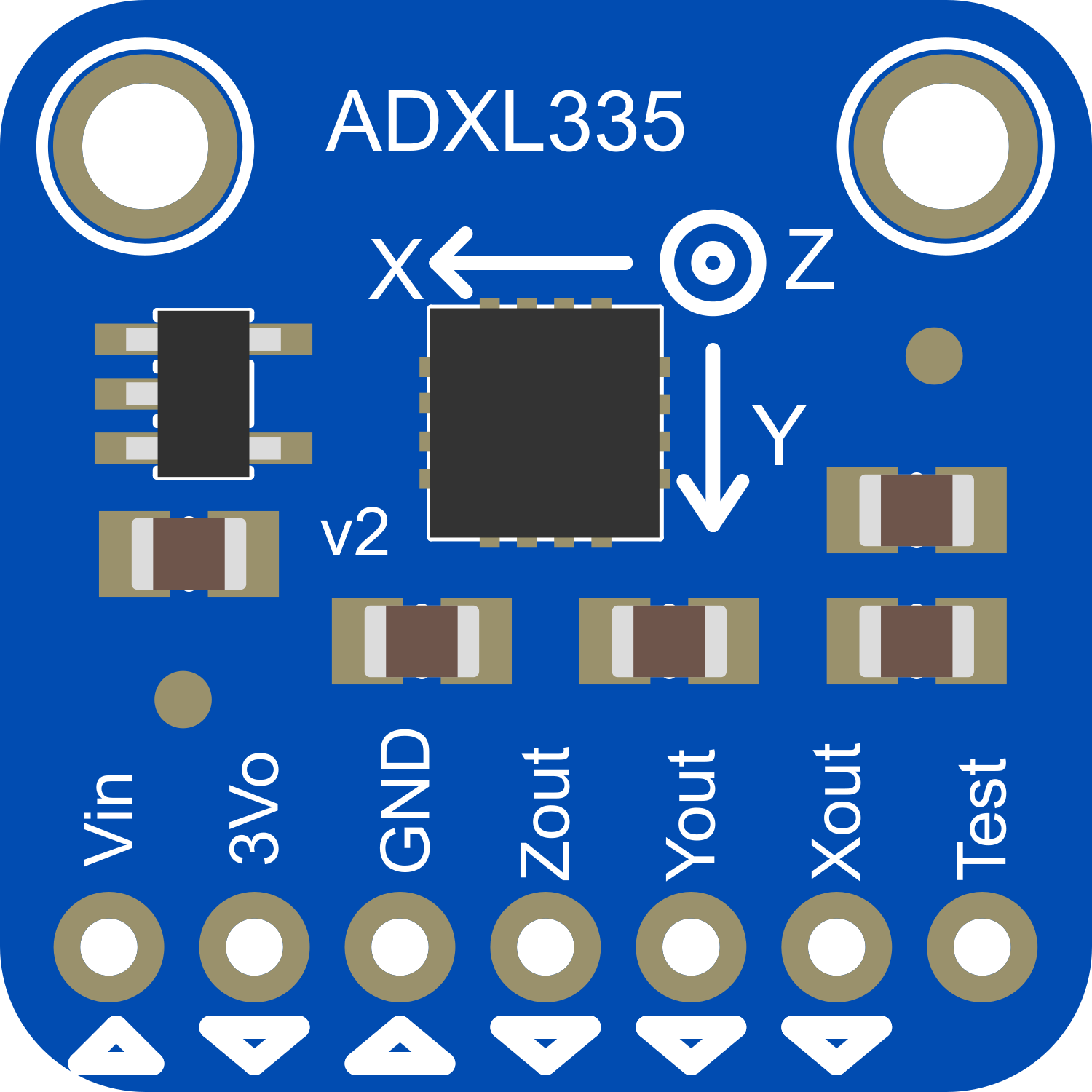
The Adafruit ADXL335 is a small, thin, low-power, complete 3-axis accelerometer with signal-conditioned voltage outputs. The product measures acceleration with a minimum full-scale range of ±3 g. It can measure the static acceleration of gravity in tilt-sensing applications, as well as dynamic acceleration resulting from motion, shock, or vibration. The ADXL335 is commonly used in electronic projects involving motion detection, tilt sensing, and vibration measurement, such as in mobile devices, gaming systems, and sports equipment.
Explore Projects Built with Adafruit ADXL335
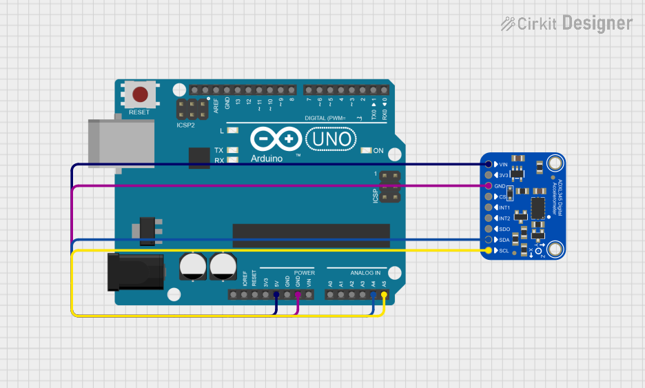
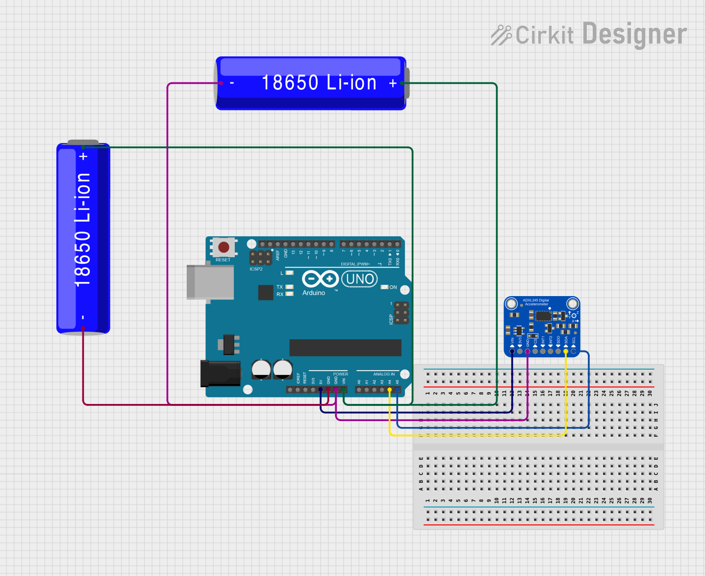
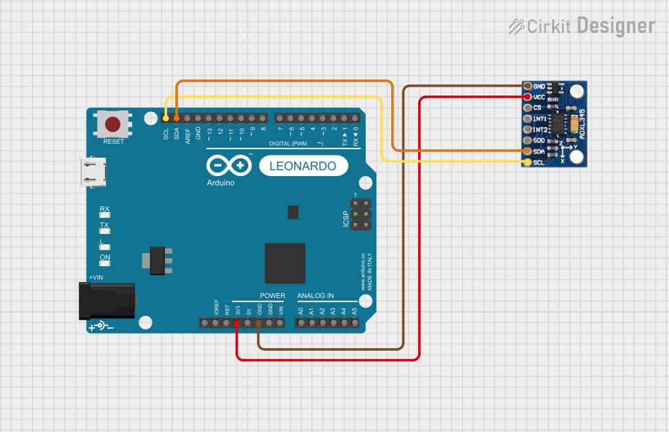
Explore Projects Built with Adafruit ADXL335
Technical Specifications
Key Technical Details
- Power Supply: 1.8V to 3.6V DC
- Sensitivity: Typically 300 mV/g at 3V
- Measurement Range: ±3 g on three axes (X, Y, Z)
- Bandwidth: Selectable between 0.5 Hz and 1600 Hz
- Temperature Range: -40°C to +85°C
- Zero-g Bias Level: XOUT = 1.5V, YOUT = 1.5V, ZOUT = 1.5V (Typical at V_S = 3V)
Pin Configuration and Descriptions
| Pin Number | Name | Description |
|---|---|---|
| 1 | NC | No Connection (Unused) |
| 2 | Z-OUT | Z-axis output |
| 3 | Y-OUT | Y-axis output |
| 4 | X-OUT | X-axis output |
| 5 | GND | Ground |
| 6 | VCC | Power supply (1.8V to 3.6V) |
| 7 | ST | Self-test (Leave unconnected for normal operation) |
| 8 | NC | No Connection (Unused) |
Usage Instructions
Integration with a Circuit
To use the ADXL335 in a circuit, follow these steps:
- Connect the VCC pin to a power supply between 1.8V and 3.6V.
- Connect the GND pin to the ground of your power supply.
- The X-OUT, Y-OUT, and Z-OUT pins provide analog voltage outputs that are proportional to the acceleration on their respective axes. Connect these to the analog inputs of your microcontroller or data acquisition system.
- If required, use capacitors for filtering as suggested in the datasheet.
Best Practices
- Ensure that the power supply is stable and within the specified voltage range.
- Avoid physical shock and vibration during operation that exceeds the measurement range.
- Use appropriate filtering capacitors to minimize noise in the output signal.
- When mounting the ADXL335, ensure that it is securely attached to the surface whose acceleration is being measured.
Example Code for Arduino UNO
// Include the Arduino Wire library for I2C
#include <Wire.h>

// ADXL335 Analog pins connected to Arduino
const int xPin = A0;
const int yPin = A1;
const int zPin = A2;

void setup() {
  // Initialize the Serial communication
  Serial.begin(9600);
}

void loop() {
  // Read the analog values from the accelerometer
  int xRead = analogRead(xPin);
  int yRead = analogRead(yPin);
  int zRead = analogRead(zPin);

  // Convert the analog values to acceleration in 'g's
  float xVoltage = (xRead / 1024.0) * 5; // Convert to voltage
  float yVoltage = (yRead / 1024.0) * 5;
  float zVoltage = (zRead / 1024.0) * 5;

  float xAccel = (xVoltage - 1.5) / 0.3; // Convert to 'g's
  float yAccel = (yVoltage - 1.5) / 0.3;
  float zAccel = (zVoltage - 1.5) / 0.3;

  // Print the acceleration values to the Serial monitor
  Serial.print("X: ");
  Serial.print(xAccel);
  Serial.print("g, Y: ");
  Serial.print(yAccel);
  Serial.print("g, Z: ");
  Serial.println(zAccel);
  Serial.println("g");

  // Delay before the next reading
  delay(100);
}
Troubleshooting and FAQs
Common Issues
- Inaccurate Readings: Ensure that the power supply is stable and that the accelerometer is properly calibrated. Check for any loose connections.
- No Output Signal: Verify that the VCC and GND pins are correctly connected and that the power supply is within the specified range.
- Noise in Signal: Use capacitors for filtering and keep the power supply and signal lines away from sources of electrical noise.
FAQs
Q: Can the ADXL335 be used to measure rotation? A: No, the ADXL335 is an accelerometer and measures linear acceleration. For rotation, you would need a gyroscope.
Q: How can I calibrate the ADXL335? A: Calibration involves recording the output at known orientations and then using these values to correct readings in your application.
Q: What is the purpose of the self-test pin? A: The self-test pin can be used to verify the functionality of the accelerometer by applying a known force to the sensor.
Q: Can the ADXL335 be used with a 5V microcontroller like the Arduino UNO? A: Yes, but ensure that the VCC pin of the ADXL335 is connected to a 3.3V output from the Arduino UNO, and use voltage dividers or level shifters for the analog outputs if necessary.
Remember to consult the official datasheet for the Adafruit ADXL335 for more detailed information and for any updates on the component's specifications and usage.