How to Use driver egs002: Examples, Pinouts, and Specs
Introduction
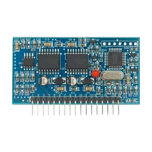
The EGS002 is a versatile driver IC designed for controlling various types of motors and actuators. It integrates advanced features for efficient power management and precise control, making it an ideal choice for applications requiring high reliability and performance. The EGS002 is commonly used in motor control systems, inverters, and other power electronics applications.
Explore Projects Built with driver egs002
Explore Projects Built with driver egs002
Common Applications and Use Cases
- Motor control for industrial and consumer applications
- DC-AC inverters for renewable energy systems
- Uninterruptible Power Supplies (UPS)
- Actuator control in robotics and automation
- High-efficiency power conversion systems
Technical Specifications
The EGS002 driver module is built around the EG8010 chip, which is a pure sine wave inverter controller. Below are the key technical specifications and pin configurations:
Key Technical Details
- Input Voltage: 12V DC (logic circuit power supply)
- Output Signal: PWM signals for driving external MOSFETs or IGBTs
- Oscillator Frequency: 12 MHz (internal crystal oscillator)
- Output Frequency: 50 Hz or 60 Hz (selectable via jumper)
- Output Waveform: Pure sine wave (via external H-bridge circuit)
- Protection Features: Over-voltage, under-voltage, over-temperature, and over-current protection
- Operating Temperature: -20°C to 85°C
- Dimensions: 50mm x 50mm (module size)
Pin Configuration and Descriptions
The EGS002 module has a 16-pin interface for connecting to external circuits. Below is the pinout and description:
| Pin Number | Pin Name | Description |
|---|---|---|
| 1 | VCC | Power supply input for the logic circuit (12V DC). |
| 2 | GND | Ground connection. |
| 3 | FREQ | Frequency selection pin (connect to GND for 50 Hz, leave open for 60 Hz). |
| 4 | VSEN | Voltage sensing input for feedback control. |
| 5 | ISEN | Current sensing input for feedback control. |
| 6 | OCP | Over-current protection input. |
| 7 | OTP | Over-temperature protection input. |
| 8 | SD | Shutdown input (active high). |
| 9 | SPWM1 | PWM output for the first half-bridge driver. |
| 10 | SPWM2 | PWM output for the second half-bridge driver. |
| 11 | SPWM3 | PWM output for the third half-bridge driver (optional, for 3-phase systems). |
| 12 | SPWM4 | PWM output for the fourth half-bridge driver (optional, for 3-phase systems). |
| 13 | NC | Not connected. |
| 14 | NC | Not connected. |
| 15 | VFB | Voltage feedback input for closed-loop control. |
| 16 | IREF | Current reference input for closed-loop control. |
Usage Instructions
How to Use the EGS002 in a Circuit
- Power Supply: Connect a regulated 12V DC power supply to the VCC and GND pins.
- Frequency Selection: Use the FREQ pin to select the desired output frequency:
- Connect to GND for 50 Hz.
- Leave the pin open for 60 Hz.
- Feedback Inputs: Connect the VSEN and ISEN pins to the appropriate voltage and current sensing circuits for closed-loop control.
- PWM Outputs: Use the SPWM1 and SPWM2 pins to drive the gates of external MOSFETs or IGBTs in an H-bridge configuration.
- Protection Features: Ensure proper connections to the OCP and OTP pins for over-current and over-temperature protection.
- Shutdown Control: Use the SD pin to enable or disable the module (active high).
Important Considerations and Best Practices
- Use proper heat sinks and cooling mechanisms for external MOSFETs or IGBTs to prevent overheating.
- Ensure that the feedback sensing circuits (VSEN and ISEN) are properly calibrated for accurate control.
- Avoid exceeding the maximum input voltage (12V DC) to prevent damage to the module.
- Use decoupling capacitors near the power supply pins to reduce noise and improve stability.
Example: Connecting the EGS002 to an Arduino UNO
The EGS002 can be interfaced with an Arduino UNO for additional control and monitoring. Below is an example code snippet for generating a shutdown signal:
// Define the pin connected to the SD (Shutdown) pin of the EGS002
const int shutdownPin = 7;

void setup() {
  // Set the shutdown pin as an output
  pinMode(shutdownPin, OUTPUT);

  // Initialize the EGS002 in active mode (low signal on SD pin)
  digitalWrite(shutdownPin, LOW);
}

void loop() {
  // Example: Trigger shutdown after 10 seconds
  delay(10000); // Wait for 10 seconds
  digitalWrite(shutdownPin, HIGH); // Send high signal to SD pin to shut down the module

  // Example: Reactivate the module after 5 seconds
  delay(5000); // Wait for 5 seconds
  digitalWrite(shutdownPin, LOW); // Send low signal to SD pin to reactivate the module
}
Troubleshooting and FAQs
Common Issues and Solutions
No Output Signal
- Cause: Incorrect power supply or loose connections.
- Solution: Verify that the VCC and GND pins are properly connected to a 12V DC power supply.
Overheating of MOSFETs
- Cause: Insufficient cooling or improper gate drive signals.
- Solution: Use appropriate heat sinks and ensure that the SPWM outputs are correctly connected to the MOSFET gates.
Inconsistent Output Frequency
- Cause: Incorrect frequency selection or unstable power supply.
- Solution: Check the FREQ pin configuration and ensure a stable 12V DC input.
Module Does Not Respond to Shutdown Signal
- Cause: Incorrect wiring or faulty Arduino code.
- Solution: Verify the connection between the Arduino and the SD pin. Check the Arduino code for errors.
FAQs
Q: Can the EGS002 be used for 3-phase motor control?
A: Yes, the SPWM3 and SPWM4 outputs can be used for 3-phase systems.Q: What is the maximum output power of the EGS002?
A: The output power depends on the external MOSFETs or IGBTs used in the circuit.Q: How do I reset the module after a fault condition?
A: Remove the fault condition (e.g., over-current or over-temperature) and toggle the SD pin to reactivate the module.
This documentation provides a comprehensive guide to using the EGS002 driver module effectively. For further assistance, refer to the manufacturer's datasheet or contact technical support.