How to Use 3 channel IR sensor: Examples, Pinouts, and Specs

Introduction
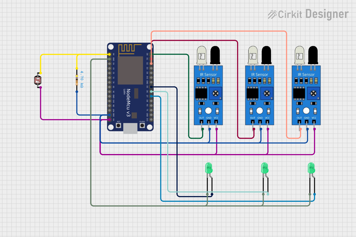
The 3 Channel IR Sensor by Funduino is a versatile infrared sensor module designed to detect infrared light reflected from objects. It features three independent IR emitter-receiver pairs, enabling it to sense objects or motion in multiple directions simultaneously. This makes it ideal for applications such as line-following robots, obstacle detection, and proximity sensing.
Explore Projects Built with 3 channel IR sensor

Explore Projects Built with 3 channel IR sensor
Common Applications
- Line-following robots
- Obstacle detection in robotics
- Proximity sensing for automation
- Edge detection for autonomous vehicles
- Motion detection in security systems
Technical Specifications
The following table outlines the key technical details of the 3 Channel IR Sensor:
| Parameter | Value |
|---|---|
| Operating Voltage | 3.3V - 5V |
| Operating Current | ~20mA |
| Detection Range | 2cm - 30cm (adjustable via potentiometer) |
| Output Type | Digital (High/Low) |
| Sensor Channels | 3 (independent) |
| Dimensions | 50mm x 20mm x 10mm |
Pin Configuration and Descriptions
The 3 Channel IR Sensor has a total of 6 pins. The table below describes each pin:
| Pin | Name | Description |
|---|---|---|
| 1 | VCC | Power supply input (3.3V - 5V) |
| 2 | GND | Ground connection |
| 3 | OUT1 | Digital output for Channel 1 (High when object detected, Low otherwise) |
| 4 | OUT2 | Digital output for Channel 2 (High when object detected, Low otherwise) |
| 5 | OUT3 | Digital output for Channel 3 (High when object detected, Low otherwise) |
| 6 | EN | Enable pin (optional, used to enable/disable the sensor module) |
Usage Instructions
How to Use the Component in a Circuit
- Power the Sensor: Connect the
VCCpin to a 3.3V or 5V power source and theGNDpin to ground. - Connect Outputs: Connect the
OUT1,OUT2, andOUT3pins to the digital input pins of your microcontroller or logic circuit. - Adjust Sensitivity: Use the onboard potentiometers to adjust the detection range for each channel.
- Enable the Sensor: If the
ENpin is used, connect it to a HIGH signal to enable the sensor. Leave it unconnected or LOW to disable the module.
Important Considerations and Best Practices
- Avoid Ambient IR Interference: Ensure the sensor is not exposed to strong ambient IR sources (e.g., sunlight) as this may affect accuracy.
- Mounting Distance: Maintain a proper distance between the sensor and the surface to avoid false detections.
- Power Supply Stability: Use a stable power supply to ensure consistent performance.
- Testing Before Deployment: Test the sensor in the actual environment to fine-tune the potentiometers for optimal performance.
Example: Connecting to an Arduino UNO
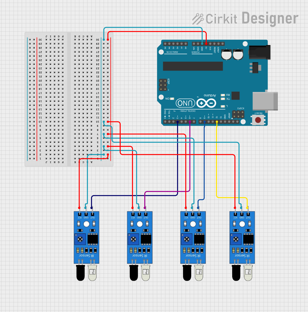
Below is an example of how to connect and use the 3 Channel IR Sensor with an Arduino UNO:
Circuit Connections
- Connect
VCCto the Arduino's5Vpin. - Connect
GNDto the Arduino'sGNDpin. - Connect
OUT1,OUT2, andOUT3to Arduino digital pins2,3, and4, respectively.
Arduino Code
// Define the pins for the 3 Channel IR Sensor
const int sensor1Pin = 2; // Channel 1 output connected to digital pin 2
const int sensor2Pin = 3; // Channel 2 output connected to digital pin 3
const int sensor3Pin = 4; // Channel 3 output connected to digital pin 4

void setup() {
  // Initialize serial communication for debugging
  Serial.begin(9600);

  // Set sensor pins as inputs
  pinMode(sensor1Pin, INPUT);
  pinMode(sensor2Pin, INPUT);
  pinMode(sensor3Pin, INPUT);
}

void loop() {
  // Read the sensor outputs
  int sensor1State = digitalRead(sensor1Pin);
  int sensor2State = digitalRead(sensor2Pin);
  int sensor3State = digitalRead(sensor3Pin);

  // Print the sensor states to the Serial Monitor
  Serial.print("Sensor 1: ");
  Serial.print(sensor1State);
  Serial.print(" | Sensor 2: ");
  Serial.print(sensor2State);
  Serial.print(" | Sensor 3: ");
  Serial.println(sensor3State);

  // Add a small delay for stability
  delay(100);
}
Troubleshooting and FAQs
Common Issues and Solutions
Sensor Not Detecting Objects
- Cause: Incorrect power supply or loose connections.
- Solution: Verify that the
VCCandGNDpins are properly connected and the power supply is within the specified range.
False Detections
- Cause: Ambient IR interference or incorrect sensitivity settings.
- Solution: Adjust the potentiometers to fine-tune the detection range and avoid strong IR sources.
No Output Signal
- Cause: Faulty wiring or disabled sensor.
- Solution: Check the connections to the
OUTpins and ensure theENpin is HIGH (if used).
Inconsistent Readings
- Cause: Unstable power supply or reflective surfaces.
- Solution: Use a stable power source and test the sensor on different surfaces.
FAQs
Q: Can the sensor detect transparent objects?
A: The sensor may struggle to detect transparent objects as they reflect minimal IR light. Use opaque or reflective surfaces for best results.
Q: How do I increase the detection range?
A: Adjust the onboard potentiometers to increase the sensitivity and detection range.
Q: Can I use this sensor with a 3.3V microcontroller?
A: Yes, the sensor operates within a voltage range of 3.3V to 5V, making it compatible with 3.3V microcontrollers like the ESP32.
Q: What is the purpose of the EN pin?
A: The EN pin allows you to enable or disable the sensor module programmatically. If not used, the sensor remains enabled by default.