
How to Use 4060: Examples, Pinouts, and Specs
 Design with 4060 in Cirkit Designer
Introduction
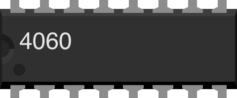
The 4060 is a binary ripple counter and oscillator integrated circuit (IC) designed for frequency division and timing applications. It features a built-in oscillator that eliminates the need for an external clock source in many designs. The IC can count up to 15 in binary, making it a versatile component for digital circuits requiring precise timing or frequency division. Its compact design and ease of use make it a popular choice in applications such as LED blinking circuits, clock generation, and time delay circuits.
Explore Projects Built with 4060
 Open Project in Cirkit Designer
 Open Project in Cirkit Designer
 Open Project in Cirkit Designer
 Open Project in Cirkit Designer
Explore Projects Built with 4060
Open Project in Cirkit DesignerOpen Project in Cirkit DesignerOpen Project in Cirkit DesignerOpen Project in Cirkit DesignerCommon Applications
- Frequency division for clock signals
- LED blinking circuits
- Time delay generation
- Pulse generation
- Digital timing circuits
Technical Specifications
The 4060 IC is a CMOS-based device with the following key specifications:
| Parameter | Value |
|---|---|
| Supply Voltage (Vcc) | 3V to 15V |
| Maximum Clock Frequency | 10 MHz (at 10V supply) |
| Output Current (per pin) | ±10 mA |
| Operating Temperature Range | -55°C to +125°C |
| Oscillator Frequency Range | Configurable via external RC network |
| Package Types | DIP-16, SOIC-16 |
Pin Configuration and Descriptions
The 4060 IC comes in a 16-pin package. Below is the pinout and description:
| Pin Number | Pin Name | Description |
|---|---|---|
| 1 | Q12 | Output pin for the 12th stage of the counter |
| 2 | Q13 | Output pin for the 13th stage of the counter |
| 3 | Q14 | Output pin for the 14th stage of the counter |
| 4 | Q4 | Output pin for the 4th stage of the counter |
| 5 | Q5 | Output pin for the 5th stage of the counter |
| 6 | Q6 | Output pin for the 6th stage of the counter |
| 7 | VSS | Ground (0V) |
| 8 | OSC1 | Oscillator input pin (connect to RC network) |
| 9 | OSC2 | Oscillator output pin (connect to RC network) |
| 10 | RESET | Active HIGH reset pin (resets the counter to 0) |
| 11 | Q10 | Output pin for the 10th stage of the counter |
| 12 | Q8 | Output pin for the 8th stage of the counter |
| 13 | Q9 | Output pin for the 9th stage of the counter |
| 14 | Q7 | Output pin for the 7th stage of the counter |
| 15 | VDD | Positive supply voltage |
| 16 | Q11 | Output pin for the 11th stage of the counter |
Usage Instructions
Using the 4060 in a Circuit
- Power Supply: Connect the VDD pin (15) to the positive supply voltage (3V to 15V) and the VSS pin (7) to ground.
- Oscillator Setup:
- Connect an external resistor (R) between OSC1 (8) and OSC2 (9).
- Connect a capacitor (C) between OSC1 (8) and ground.
- The values of R and C determine the oscillator frequency. Use the formula: [ f = \frac{1}{2.2 \cdot R \cdot C} ]
- Reset Function: To reset the counter, apply a HIGH signal to the RESET pin (10). This will reset all outputs to 0.
- Output Pins: Use the output pins (Q4 to Q14) to obtain divided clock signals. Each output pin represents a specific division of the oscillator frequency.
Example Circuit
Below is an example of a simple LED blinking circuit using the 4060 IC:
+Vcc
  |
  R
  |
 OSC1 (Pin 8) ----->|-----> OSC2 (Pin 9)
  |                 |
  C                 |
  |                 |
 GND               GND
Arduino UNO Example Code
The 4060 can be used with an Arduino UNO to monitor its output signals. Below is an example code to read the Q4 output pin:
// Define the pin connected to Q4 of the 4060
const int q4Pin = 2; // Connect Q4 to Arduino digital pin 2

void setup() {
  pinMode(q4Pin, INPUT); // Set Q4 pin as input
  Serial.begin(9600);    // Initialize serial communication
}

void loop() {
  int q4State = digitalRead(q4Pin); // Read the state of Q4
  Serial.print("Q4 State: ");
  Serial.println(q4State); // Print the state to the Serial Monitor
  delay(500); // Wait for 500ms
}
Important Considerations
- Ensure the supply voltage does not exceed the maximum rating of 15V.
- Use decoupling capacitors (e.g., 0.1 µF) near the VDD pin to reduce noise.
- Avoid leaving unused input pins floating; connect them to VDD or VSS.
Troubleshooting and FAQs
Common Issues
Oscillator Not Working:
- Check the connections of the resistor and capacitor in the RC network.
- Ensure the values of R and C are appropriate for the desired frequency.
No Output Signal:
- Verify the power supply connections to VDD and VSS.
- Ensure the RESET pin is not held HIGH, as this will disable the outputs.
Incorrect Frequency Division:
- Double-check the RC network values and the output pin being used.
- Ensure the oscillator frequency is stable.
FAQs
Q: Can I use a crystal oscillator with the 4060?
A: Yes, the 4060 can work with a crystal oscillator. Connect the crystal between OSC1 and OSC2, and add small capacitors (e.g., 22 pF) to ground.
Q: What happens if the RESET pin is left floating?
A: The RESET pin should not be left floating. Connect it to ground (VSS) if not in use to ensure proper operation.
Q: How do I calculate the output frequency for a specific pin?
A: The output frequency for each pin is the oscillator frequency divided by ( 2^n ), where ( n ) is the stage number of the pin (e.g., Q4 = ( 2^4 )).
By following this documentation, you can effectively use the 4060 IC in your projects for reliable timing and frequency division.