How to Use 1 Channel Relay module with Optocoupler: Examples, Pinouts, and Specs
Introduction
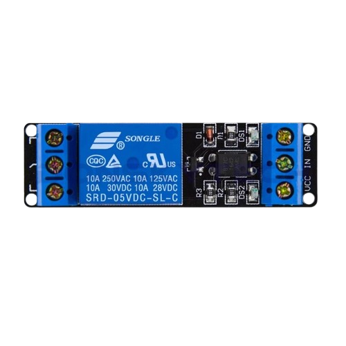
The 1 Channel Relay Module with Optocoupler (Manufacturer Part ID: SRD-05VDC-SL-C) is a versatile electronic component designed to control high-voltage devices using low-voltage signals. Manufactured by Songle, this module features an optocoupler for electrical isolation, ensuring safe operation by protecting the control circuit from high-voltage spikes or surges.
This relay module is widely used in home automation, industrial control systems, and DIY electronics projects. It is particularly popular for applications requiring the control of AC appliances, such as lights, fans, and motors, using microcontrollers like Arduino, Raspberry Pi, or other low-power control systems.
Explore Projects Built with 1 Channel Relay module with Optocoupler


Explore Projects Built with 1 Channel Relay module with Optocoupler
Technical Specifications
Key Technical Details
- Relay Type: Electromechanical
- Control Voltage (VCC): 5V DC
- Trigger Voltage: 0-5V DC (Low-level trigger)
- Relay Output: Supports AC (250V/10A) or DC (30V/10A) loads
- Optocoupler Isolation: Yes
- Power Consumption: ~70mA when active
- Dimensions: 50mm x 26mm x 18.5mm (L x W x H)
- Weight: ~15g
- Indicator LED: Onboard LED to indicate relay activation
Pin Configuration and Descriptions
The module has two sets of pins: Control Pins and Relay Output Terminals.
Control Pins
| Pin Name | Description |
|---|---|
| VCC | Connect to the 5V power supply of the control circuit. |
| GND | Connect to the ground of the control circuit. |
| IN | Control signal input. A LOW signal (0V) activates the relay. |
Relay Output Terminals
| Terminal Name | Description |
|---|---|
| NO (Normally Open) | The load is disconnected when the relay is inactive. Closes when active. |
| COM (Common) | Common terminal for the load connection. |
| NC (Normally Closed) | The load is connected when the relay is inactive. Opens when active. |
Usage Instructions
How to Use the Component in a Circuit
- Power the Module: Connect the VCC pin to a 5V DC power source and the GND pin to the ground of your control circuit.
- Control Signal: Connect the IN pin to the digital output pin of a microcontroller (e.g., Arduino). A LOW signal (0V) will activate the relay.
- Load Connection:
- Connect the high-voltage device (e.g., light bulb, fan) to the COM and NO terminals if you want the device to turn on when the relay is activated.
- Use the COM and NC terminals if you want the device to turn off when the relay is activated.
- Indicator LED: Observe the onboard LED, which lights up when the relay is active.
Important Considerations and Best Practices
- Electrical Isolation: The optocoupler ensures isolation between the control circuit and the high-voltage load. This protects sensitive components like microcontrollers from voltage spikes.
- Load Ratings: Ensure the connected load does not exceed the relay's maximum ratings (250V AC/10A or 30V DC/10A).
- Flyback Diode: For inductive loads (e.g., motors), use a flyback diode across the load to suppress voltage spikes.
- Low-Level Trigger: The relay is activated by a LOW signal (0V) on the IN pin. Ensure your microcontroller's logic level matches this requirement.
Example: Connecting to an Arduino UNO
Below is an example of how to control the relay module using an Arduino UNO:
Circuit Connections
- VCC → Arduino 5V
- GND → Arduino GND
- IN → Arduino Digital Pin 7
- COM → One terminal of the load (e.g., light bulb)
- NO → Other terminal of the load
- Connect the load to an external power source as required.
Arduino Code
// Define the relay control pin
const int relayPin = 7;

void setup() {
  // Set the relay pin as an output
  pinMode(relayPin, OUTPUT);

  // Ensure the relay is off initially
  digitalWrite(relayPin, HIGH); // HIGH = Relay off (low-level trigger)
}

void loop() {
  // Turn the relay on (activate the load)
  digitalWrite(relayPin, LOW); // LOW = Relay on
  delay(5000); // Keep the relay on for 5 seconds

  // Turn the relay off (deactivate the load)
  digitalWrite(relayPin, HIGH); // HIGH = Relay off
  delay(5000); // Keep the relay off for 5 seconds
}
Notes:
- The relay is active LOW, meaning a LOW signal (0V) on the IN pin will activate it.
- Always double-check your connections, especially when working with high-voltage loads.
Troubleshooting and FAQs
Common Issues and Solutions
Relay Not Activating:
- Ensure the VCC and GND pins are properly connected to a 5V power source.
- Verify that the control signal on the IN pin is LOW (0V) to activate the relay.
- Check the onboard LED. If it does not light up, the relay may not be receiving the correct signal.
Load Not Turning On/Off:
- Confirm that the load is correctly connected to the COM and NO (or NC) terminals.
- Ensure the load's power source is properly connected and functional.
- Verify that the load does not exceed the relay's maximum ratings.
Microcontroller Resetting or Malfunctioning:
- This may occur due to voltage spikes from inductive loads. Add a flyback diode across the load to suppress these spikes.
- Ensure proper electrical isolation between the control circuit and the high-voltage load.
Relay Clicking but No Load Response:
- Check the wiring of the load and ensure it is securely connected.
- Test the relay with a multimeter to confirm that the contacts are switching correctly.
FAQs
Q1: Can I use this relay module with a 3.3V microcontroller?
A1: Yes, but you may need a level shifter or transistor to ensure the control signal is compatible with the relay's 5V logic.
Q2: Is the relay module safe for controlling AC appliances?
A2: Yes, as long as the load does not exceed the relay's maximum ratings (250V AC/10A). Always follow proper safety precautions when working with high voltage.
Q3: Can I control multiple relays with one microcontroller?
A3: Yes, you can control multiple relay modules by connecting each module's IN pin to a separate digital output pin on the microcontroller.
Q4: What is the purpose of the optocoupler?
A4: The optocoupler provides electrical isolation between the control circuit and the high-voltage load, protecting sensitive components from voltage spikes or surges.