How to Use PMIC: Examples, Pinouts, and Specs
Introduction
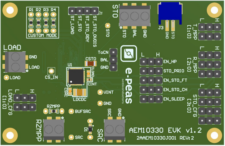
The AEM10330 is a Power Management Integrated Circuit (PMIC) manufactured by e-peas. It is designed to efficiently manage the power requirements of electronic systems, particularly in energy-harvesting applications. This PMIC integrates voltage regulation, battery management, and power sequencing functionalities, making it ideal for low-power IoT devices, wearable electronics, and other energy-sensitive applications.
Explore Projects Built with PMIC


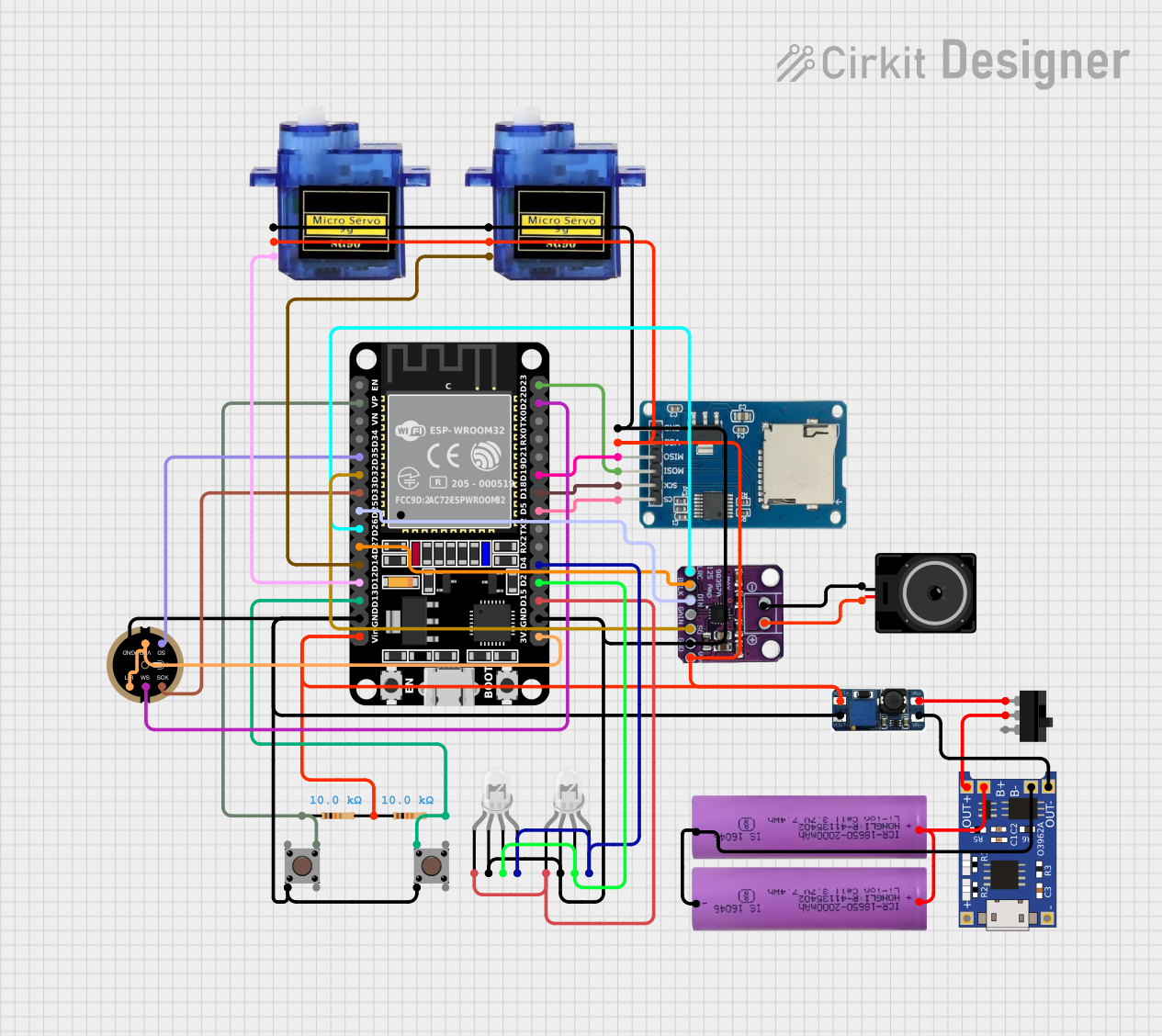

Explore Projects Built with PMIC
Common Applications and Use Cases
- Energy harvesting from solar panels, thermoelectric generators, or piezoelectric sources
- Battery-powered IoT devices
- Wearable electronics
- Wireless sensor networks
- Industrial monitoring systems
Technical Specifications
The AEM10330 is optimized for ultra-low-power applications and offers the following key specifications:
Key Technical Details
- Input Voltage Range: 100 mV to 4.5 V
- Output Voltage Options: Configurable (1.2 V, 1.8 V, 2.5 V, 3.3 V, etc.)
- Quiescent Current: Ultra-low (as low as 400 nA)
- Maximum Input Power: Up to 50 mW
- Battery Management: Supports rechargeable batteries (Li-ion, Li-Po, supercapacitors)
- Energy Storage: Compatible with capacitors and batteries
- Integrated Protection: Overvoltage, undervoltage, and overcurrent protection
- Operating Temperature Range: -40°C to +85°C
- Package: QFN28 (4 mm x 4 mm)
Pin Configuration and Descriptions
The AEM10330 features a 28-pin QFN package. Below is the pinout and description:
| Pin Number | Pin Name | Description |
|---|---|---|
| 1 | VIN | Input voltage from the energy source (e.g., solar panel, TEG) |
| 2 | GND | Ground connection |
| 3 | VOUT1 | Primary regulated output voltage |
| 4 | VOUT2 | Secondary regulated output voltage |
| 5 | VBAT | Battery connection for energy storage |
| 6 | EN | Enable pin to activate or deactivate the PMIC |
| 7 | MPPT | Maximum Power Point Tracking configuration pin |
| 8 | VSTORE | Energy storage capacitor connection |
| 9-28 | NC/Other | Reserved or no-connect pins (refer to the datasheet for detailed pin functions) |
Usage Instructions
The AEM10330 is designed to simplify power management in energy-harvesting systems. Follow these steps to integrate it into your circuit:
Step 1: Connect the Energy Source
- Connect the energy source (e.g., solar panel or thermoelectric generator) to the VIN pin.
- Ensure the input voltage is within the specified range (100 mV to 4.5 V).
Step 2: Configure the Output Voltages
- Use external resistors or configuration pins to set the desired output voltages on VOUT1 and VOUT2.
- Refer to the datasheet for the resistor values corresponding to specific voltage levels.
Step 3: Connect the Energy Storage
- Attach a rechargeable battery or supercapacitor to the VBAT pin for energy storage.
- Use the VSTORE pin to connect an additional capacitor for temporary energy storage.
Step 4: Enable the PMIC
- Use the EN pin to enable or disable the PMIC. Pull the pin high to activate the circuit.
Step 5: Optimize Energy Harvesting
- Configure the MPPT pin to enable Maximum Power Point Tracking for optimal energy harvesting.
- Adjust the MPPT settings based on the characteristics of your energy source.
Example: Using the AEM10330 with an Arduino UNO
The AEM10330 can be used to power an Arduino UNO in energy-harvesting applications. Below is an example of how to connect the PMIC to the Arduino and monitor the output voltage:
Circuit Connections
- Connect the VOUT1 pin of the AEM10330 to the Arduino's VIN pin.
- Connect the GND pin of the AEM10330 to the Arduino's GND pin.
- Use a solar panel as the input source and connect it to the VIN pin of the AEM10330.
Arduino Code Example
// Example code to monitor the output voltage of the AEM10330 using Arduino UNO
const int voltagePin = A0; // Analog pin to read the output voltage
float voltage = 0.0;

void setup() {
  Serial.begin(9600); // Initialize serial communication
  pinMode(voltagePin, INPUT); // Set the voltage pin as input
}

void loop() {
  int sensorValue = analogRead(voltagePin); // Read the analog value
  voltage = sensorValue * (5.0 / 1023.0); // Convert to voltage (assuming 5V reference)

  // Print the voltage to the Serial Monitor
  Serial.print("Output Voltage: ");
  Serial.print(voltage);
  Serial.println(" V");

  delay(1000); // Wait for 1 second before the next reading
}
Important Considerations and Best Practices
- Ensure the input voltage does not exceed the maximum rating of 4.5 V to avoid damaging the PMIC.
- Use appropriate capacitors on the VSTORE and VBAT pins to stabilize the energy storage.
- Configure the MPPT settings based on the energy source for maximum efficiency.
- Avoid leaving unused pins floating; connect them to ground or as specified in the datasheet.
Troubleshooting and FAQs
Common Issues and Solutions
No Output Voltage
- Verify that the input voltage is within the specified range.
- Check the EN pin to ensure the PMIC is enabled.
- Confirm that the energy storage (battery or capacitor) is properly connected.
Low Efficiency
- Ensure the MPPT settings are correctly configured for the energy source.
- Minimize losses by using low-resistance connections and high-quality components.
Overheating
- Check for excessive input power beyond the PMIC's maximum rating.
- Ensure proper thermal management and adequate ventilation.
FAQs
Can the AEM10330 work with non-rechargeable batteries?
- No, the AEM10330 is designed for use with rechargeable batteries or supercapacitors.
What is the maximum power the AEM10330 can handle?
- The PMIC can handle up to 50 mW of input power.
How do I configure the output voltages?
- Use external resistors or configuration pins as specified in the datasheet to set the desired output voltage levels.
By following this documentation, users can effectively integrate the AEM10330 into their energy-harvesting systems and optimize power management for their applications.