Cirkit Designer Logo
Cirkit Designer
Your all-in-one circuit design IDE
Home / 
Component Documentation

How to Use endstop mechanical limit switch ramps 1.4: Examples, Pinouts, and Specs

Image of endstop mechanical limit switch ramps 1.4
Cirkit Designer LogoDesign with endstop mechanical limit switch ramps 1.4 in Cirkit Designer

Introduction

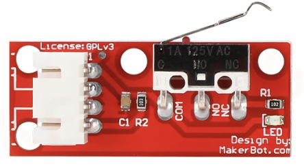
The Endstop Mechanical Limit Switch is a simple yet essential component used in 3D printers, CNC machines, and other automated systems. It is designed to detect the physical limits of motion for an axis, ensuring precise positioning and preventing mechanical damage. This component is commonly used with the RAMPS 1.4 board, which is a popular control board for 3D printers.

Explore Projects Built with endstop mechanical limit switch ramps 1.4

Use Cirkit Designer to design, explore, and prototype these projects online. Some projects support real-time simulation. Click "Open Project" to start designing instantly!
Arduino Mega 2560 and RAMPS 1.4 Based Stepper Motor Control System with Limit Switches
Image of Arduino Robotics Arm: A project utilizing endstop mechanical limit switch ramps 1.4 in a practical application
This circuit is a 3D printer control system using an Arduino Mega 2560 and a RAMPS 1.4 shield to manage multiple stepper motors and limit switches. The stepper motors are driven by A4988 drivers, and the system is powered by a 12V power supply. The setup includes limit switches for end-stop detection and a ULN2003 driver for an additional stepper motor.
Cirkit Designer LogoOpen Project in Cirkit Designer
CNC Machine with Limit Switch Integration
Image of CNC: A project utilizing endstop mechanical limit switch ramps 1.4 in a practical application
This circuit connects a limit switch to a CNC machine, allowing the CNC to receive signals from the limit switch. The limit switch is powered by the CNC's 3.3V supply and shares a common ground with the CNC.
Cirkit Designer LogoOpen Project in Cirkit Designer
Arduino Mega 2560 and RAMPS 1.4 Controlled 3D Printer with Stepper Motors and Limit Switches
Image of Copy of Arduino Robotics Arm: A project utilizing endstop mechanical limit switch ramps 1.4 in a practical application
This circuit is a 3D printer control system using a RAMPS 1.4 shield connected to an Arduino Mega 2560. It controls multiple stepper motors via A4988 drivers and includes limit switches for position sensing, powered by a 12V power supply.
Cirkit Designer LogoOpen Project in Cirkit Designer
Battery-Powered Motor Control System with Toggle and Limit Switches
Image of Simple Lift: A project utilizing endstop mechanical limit switch ramps 1.4 in a practical application
This circuit controls a hobby gear motor using two toggle switches, a rocker switch, and two limit switches. The motor's direction is controlled by the toggle switches, while the limit switches and rocker switch provide additional control and safety features. Power is supplied by a 18650 battery in a holder.
Cirkit Designer LogoOpen Project in Cirkit Designer

Explore Projects Built with endstop mechanical limit switch ramps 1.4

Use Cirkit Designer to design, explore, and prototype these projects online. Some projects support real-time simulation. Click "Open Project" to start designing instantly!
Image of Arduino Robotics Arm: A project utilizing endstop mechanical limit switch ramps 1.4 in a practical application
Arduino Mega 2560 and RAMPS 1.4 Based Stepper Motor Control System with Limit Switches
This circuit is a 3D printer control system using an Arduino Mega 2560 and a RAMPS 1.4 shield to manage multiple stepper motors and limit switches. The stepper motors are driven by A4988 drivers, and the system is powered by a 12V power supply. The setup includes limit switches for end-stop detection and a ULN2003 driver for an additional stepper motor.
Cirkit Designer LogoOpen Project in Cirkit Designer
Image of CNC: A project utilizing endstop mechanical limit switch ramps 1.4 in a practical application
CNC Machine with Limit Switch Integration
This circuit connects a limit switch to a CNC machine, allowing the CNC to receive signals from the limit switch. The limit switch is powered by the CNC's 3.3V supply and shares a common ground with the CNC.
Cirkit Designer LogoOpen Project in Cirkit Designer
Image of Copy of Arduino Robotics Arm: A project utilizing endstop mechanical limit switch ramps 1.4 in a practical application
Arduino Mega 2560 and RAMPS 1.4 Controlled 3D Printer with Stepper Motors and Limit Switches
This circuit is a 3D printer control system using a RAMPS 1.4 shield connected to an Arduino Mega 2560. It controls multiple stepper motors via A4988 drivers and includes limit switches for position sensing, powered by a 12V power supply.
Cirkit Designer LogoOpen Project in Cirkit Designer
Image of Simple Lift: A project utilizing endstop mechanical limit switch ramps 1.4 in a practical application
Battery-Powered Motor Control System with Toggle and Limit Switches
This circuit controls a hobby gear motor using two toggle switches, a rocker switch, and two limit switches. The motor's direction is controlled by the toggle switches, while the limit switches and rocker switch provide additional control and safety features. Power is supplied by a 18650 battery in a holder.
Cirkit Designer LogoOpen Project in Cirkit Designer

Common Applications and Use Cases

  • 3D printers for detecting the home position of axes
  • CNC machines for axis limit detection
  • Robotics for motion boundary detection
  • Any system requiring precise end-of-travel detection

Technical Specifications

  • Operating Voltage: 5V DC
  • Current Rating: 300mA (max)
  • Switch Type: Normally Open (NO) or Normally Closed (NC)
  • Connector Type: 3-pin Dupont (Signal, VCC, GND)
  • Dimensions: 32mm x 10mm x 10mm (approx.)
  • Cable Length: Typically 70cm (varies by manufacturer)

Pin Configuration and Descriptions

Pin Name Description
Signal Outputs the state of the switch (HIGH or LOW)
VCC Supplies 5V power to the switch
GND Ground connection

Usage Instructions

How to Use the Component in a Circuit

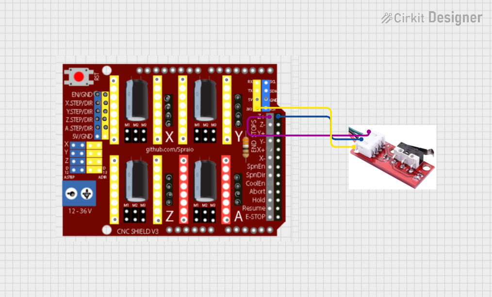
  1. Wiring the Endstop to RAMPS 1.4:

    • Connect the Signal pin of the endstop to the corresponding signal pin on the RAMPS 1.4 board.
    • Connect the VCC pin to the 5V pin on the RAMPS 1.4 board.
    • Connect the GND pin to the ground pin on the RAMPS 1.4 board.
  2. Configuring the Firmware:

    • In 3D printer firmware (e.g., Marlin), configure the endstop type (NO or NC) in the configuration file.
    • Ensure the correct pin assignments for the endstop in the firmware.
  3. Testing the Endstop:

    • Power on the system and manually trigger the endstop by pressing the switch.
    • Verify that the firmware detects the endstop activation (e.g., using the M119 command in Marlin).

Important Considerations and Best Practices

  • Debouncing: Mechanical switches may produce noise or bouncing when activated. Use firmware settings or external capacitors to debounce the signal.
  • Mounting: Securely mount the endstop to prevent misalignment or accidental triggering.
  • Polarity: Ensure correct wiring of VCC and GND to avoid damage to the switch.
  • Firmware Configuration: Double-check the firmware settings for the endstop type (NO or NC) to match the physical wiring.

Example Code for Arduino UNO

The following code demonstrates how to use the endstop with an Arduino UNO for basic testing:

// Define the pin connected to the endstop signal
const int endstopPin = 2;

// Variable to store the endstop state
int endstopState = 0;

void setup() {
  // Initialize the endstop pin as an input with pullup resistor
  pinMode(endstopPin, INPUT_PULLUP);

  // Start the serial communication for debugging
  Serial.begin(9600);
}

void loop() {
  // Read the state of the endstop (LOW when pressed, HIGH when released)
  endstopState = digitalRead(endstopPin);

  // Print the state to the serial monitor
  if (endstopState == LOW) {
    Serial.println("Endstop triggered!");
  } else {
    Serial.println("Endstop not triggered.");
  }

  // Add a small delay to avoid flooding the serial monitor
  delay(200);
}

Troubleshooting and FAQs

Common Issues and Solutions

  1. Endstop Not Detected by Firmware:

    • Solution: Check the wiring and ensure the signal pin is connected to the correct pin on the RAMPS 1.4 board. Verify the firmware configuration.
  2. Endstop Always Triggered:

    • Solution: Verify the NO/NC configuration in the firmware matches the physical wiring. Check for short circuits in the wiring.
  3. Endstop Not Triggering Consistently:

    • Solution: Ensure the switch is securely mounted and aligned with the moving part. Check for mechanical wear or damage to the switch.
  4. Noise or False Triggers:

    • Solution: Use a pullup resistor (if not already enabled) or add a small capacitor across the signal and ground pins to filter noise.

FAQs

  • Can I use this endstop with other control boards? Yes, the endstop is compatible with most control boards that support 5V logic levels.

  • What is the difference between NO and NC configurations? In NO (Normally Open) mode, the circuit is open until the switch is pressed. In NC (Normally Closed) mode, the circuit is closed until the switch is pressed.

  • How do I test the endstop without connecting it to a board? Use a multimeter to check continuity between the signal and ground pins. Pressing the switch should change the continuity state.

  • Can I extend the cable length? Yes, but ensure proper shielding to avoid signal interference, especially in noisy environments.

This documentation provides a comprehensive guide to using the Endstop Mechanical Limit Switch with RAMPS 1.4 and other compatible systems.