How to Use PY32_L9110_I2C_DRIVER: Examples, Pinouts, and Specs
Introduction
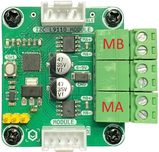
The PY32_L9110_I2C_DRIVER is a dual-channel motor driver manufactured by MakerEdu.vn (Part ID: Motor Driver). It is designed to interface with microcontrollers via the I2C protocol, enabling precise control of DC motors and stepper motors. This driver supports adjustable speed and direction control, making it ideal for robotics, automation, and other motorized applications.
Explore Projects Built with PY32_L9110_I2C_DRIVER


Explore Projects Built with PY32_L9110_I2C_DRIVER
Common Applications and Use Cases
- Robotics projects requiring motorized movement
- Automated conveyor systems
- Remote-controlled vehicles
- Stepper motor-based positioning systems
- Educational projects for learning motor control with microcontrollers
Technical Specifications
The following table outlines the key technical details of the PY32_L9110_I2C_DRIVER:
| Parameter | Value |
|---|---|
| Operating Voltage | 3.3V to 5V |
| Motor Voltage Range | 4.5V to 12V |
| Maximum Output Current | 800mA per channel |
| Communication Protocol | I2C |
| I2C Address Range | Configurable via jumpers (default: 0x10) |
| Channels | 2 (dual-channel for two motors) |
| Motor Types Supported | DC motors, Stepper motors |
| PWM Frequency | Up to 20 kHz |
| Dimensions | 40mm x 30mm x 10mm |
Pin Configuration and Descriptions
The PY32_L9110_I2C_DRIVER has the following pin layout:
| Pin Name | Type | Description |
|---|---|---|
| VCC | Power Input | Connect to 3.3V or 5V power supply. |
| GND | Ground | Connect to the ground of the power supply. |
| SCL | I2C Clock Line | Connect to the SCL pin of the microcontroller. |
| SDA | I2C Data Line | Connect to the SDA pin of the microcontroller. |
| A0, A1 | Address Select | Configure the I2C address (default: 0x10). |
| OUT1 | Motor Output | Connect to one terminal of Motor 1. |
| OUT2 | Motor Output | Connect to the other terminal of Motor 1. |
| OUT3 | Motor Output | Connect to one terminal of Motor 2. |
| OUT4 | Motor Output | Connect to the other terminal of Motor 2. |
Usage Instructions
How to Use the Component in a Circuit
- Power Supply: Connect the VCC pin to a 3.3V or 5V power source and the GND pin to ground.
- I2C Connection: Connect the SCL and SDA pins to the corresponding I2C pins on your microcontroller.
- Motor Connections: Attach the motor terminals to the OUT1, OUT2 (for Motor 1) and OUT3, OUT4 (for Motor 2) pins.
- I2C Address Configuration: Use the A0 and A1 pins to set the I2C address if multiple drivers are used in the same circuit.
- Programming: Use the microcontroller to send I2C commands to control motor speed and direction.
Important Considerations and Best Practices
- Ensure the motor voltage does not exceed the specified range (4.5V to 12V).
- Use appropriate decoupling capacitors near the power supply pins to reduce noise.
- Avoid exceeding the maximum output current of 800mA per channel to prevent damage.
- If using with an Arduino UNO, ensure pull-up resistors (4.7kΩ to 10kΩ) are present on the I2C lines.
Example Code for Arduino UNO
Below is an example Arduino sketch to control two DC motors using the PY32_L9110_I2C_DRIVER:
#include <Wire.h> // Include the Wire library for I2C communication

#define MOTOR_DRIVER_ADDR 0x10 // Default I2C address of the motor driver

void setup() {
  Wire.begin(); // Initialize I2C communication
  Serial.begin(9600); // Initialize serial communication for debugging

  // Set Motor 1 to move forward at 50% speed
  setMotor(1, 128, true); // Motor 1, speed 128 (50%), direction forward

  // Set Motor 2 to move backward at 75% speed
  setMotor(2, 192, false); // Motor 2, speed 192 (75%), direction backward
}

void loop() {
  // Add your main code here
}

// Function to control motor speed and direction
void setMotor(uint8_t motor, uint8_t speed, bool direction) {
  Wire.beginTransmission(MOTOR_DRIVER_ADDR); // Start communication
  Wire.write(motor); // Specify motor number (1 or 2)
  Wire.write(speed); // Set speed (0-255)
  Wire.write(direction ? 1 : 0); // Set direction (1 = forward, 0 = backward)
  Wire.endTransmission(); // End communication
}
Troubleshooting and FAQs
Common Issues and Solutions
Motors Not Running:
- Ensure the power supply voltage is within the specified range.
- Verify the motor connections to the OUT pins.
- Check the I2C address configuration and ensure it matches the code.
Erratic Motor Behavior:
- Add decoupling capacitors near the motor driver to reduce electrical noise.
- Ensure the I2C lines have proper pull-up resistors.
Overheating:
- Avoid exceeding the maximum current rating of 800mA per channel.
- Use heat sinks or active cooling if operating at high currents for extended periods.
I2C Communication Errors:
- Check the SCL and SDA connections for loose wires.
- Ensure the I2C address is correctly set in the code.
FAQs
Q: Can I use this driver with a Raspberry Pi?
A: Yes, the driver is compatible with any microcontroller or SBC that supports I2C communication, including Raspberry Pi.
Q: How do I control a stepper motor with this driver?
A: You can control a stepper motor by energizing the coils in the correct sequence. Refer to the stepper motor's datasheet for the sequence and use the setMotor function to control each coil.
Q: What happens if I exceed the current limit?
A: Exceeding the current limit may damage the driver. Use motors within the specified current range or add current-limiting resistors.
Q: Can I daisy-chain multiple drivers?
A: Yes, you can daisy-chain multiple drivers by configuring unique I2C addresses using the A0 and A1 pins.