How to Use Nano Extension: Examples, Pinouts, and Specs
Introduction
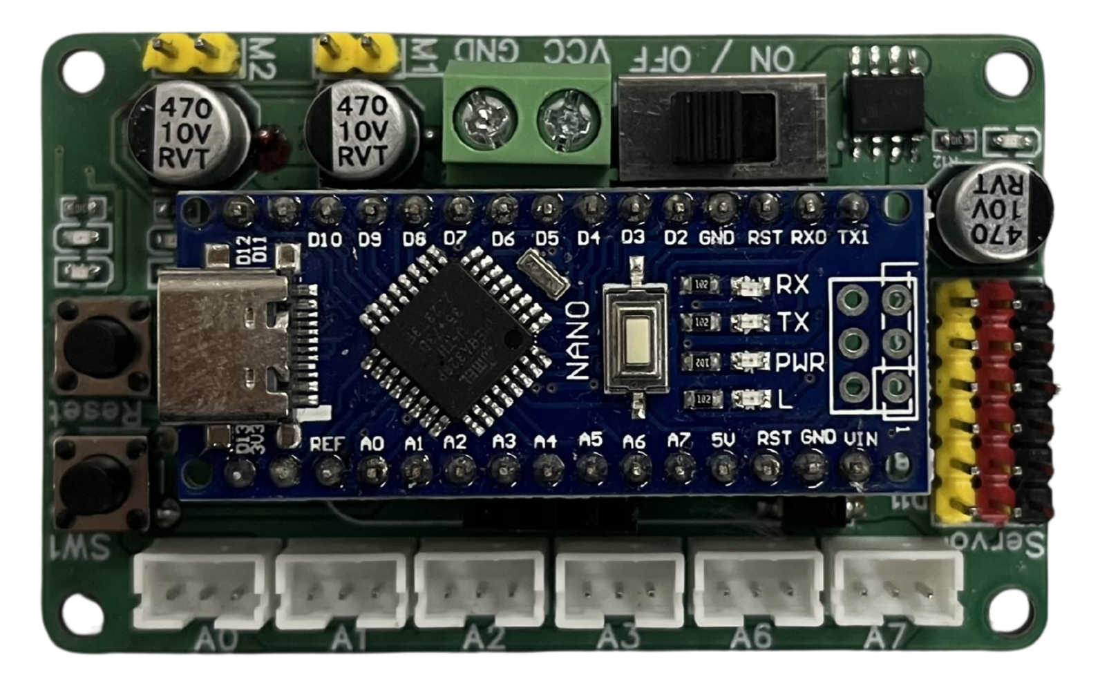
The Nano Extension by Princebot is a compact module designed to enhance the capabilities of microcontrollers or development boards, such as the Arduino Nano. This versatile module provides additional I/O ports, sensors, or communication interfaces, making it an ideal choice for expanding the functionality of your projects without increasing the overall size. Its small form factor and ease of integration make it suitable for a wide range of applications.
Explore Projects Built with Nano Extension

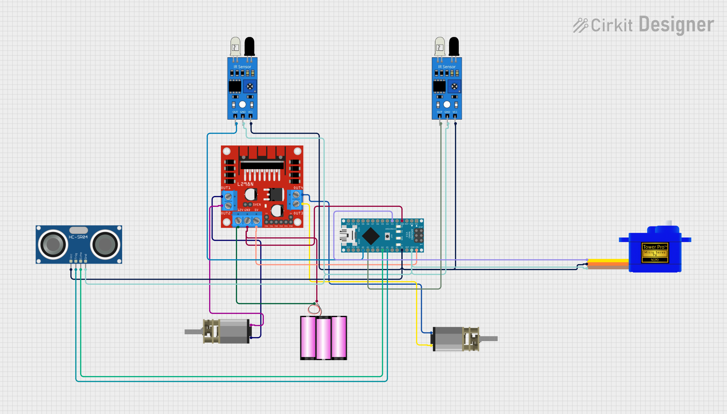
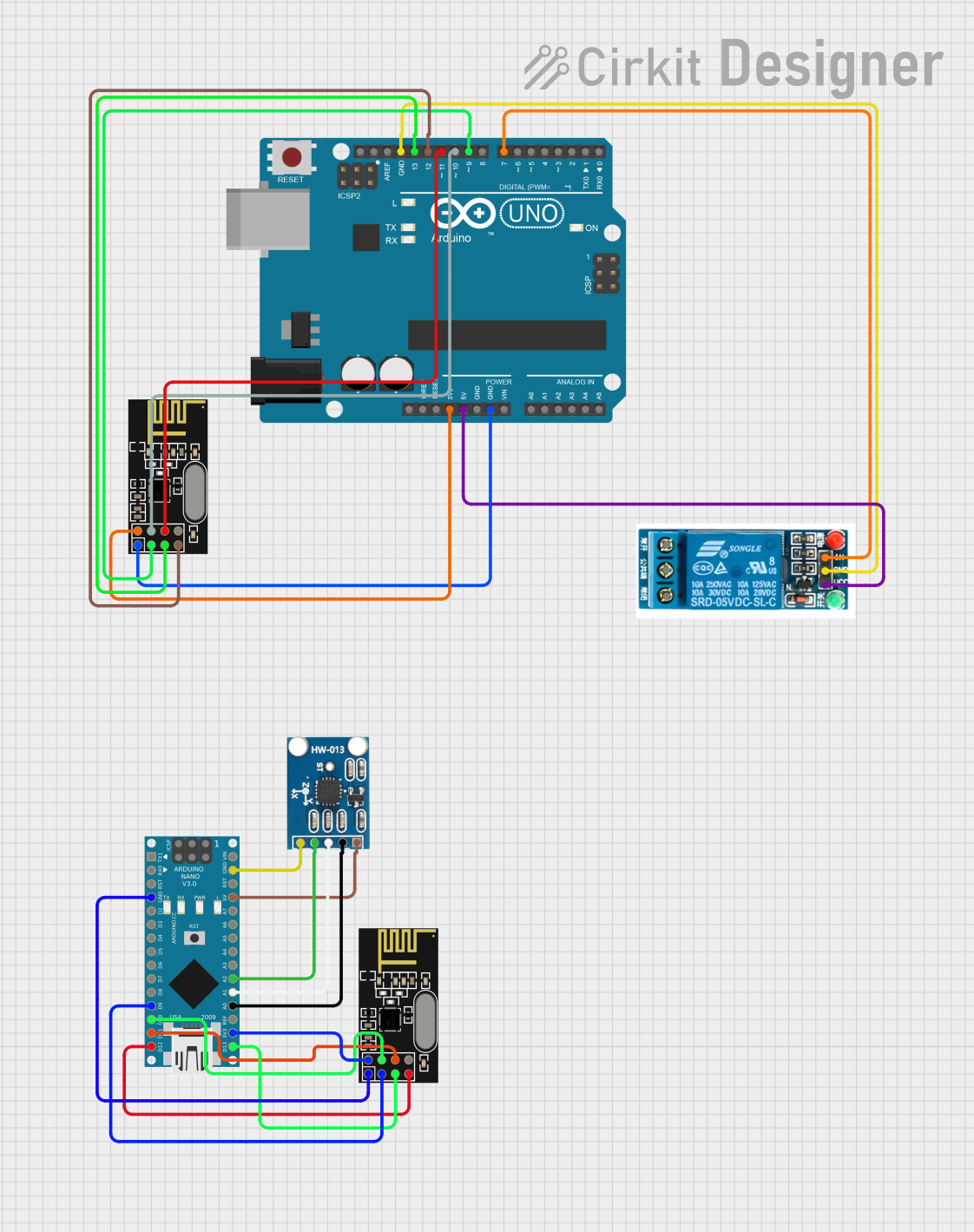
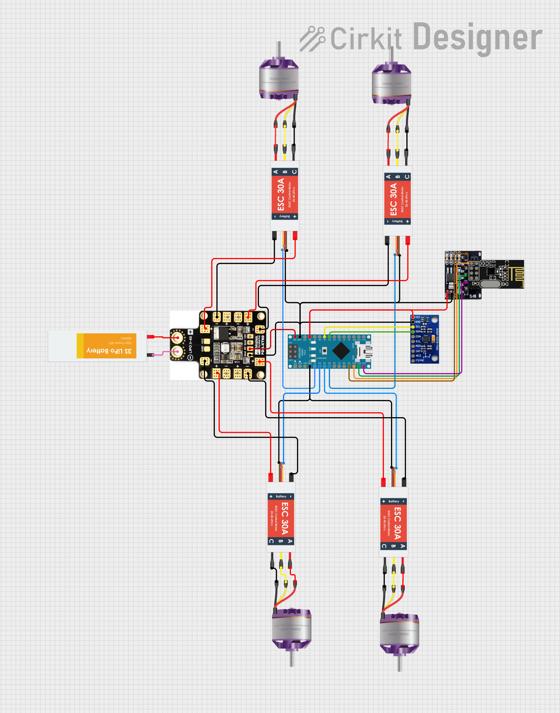
Explore Projects Built with Nano Extension
Common Applications and Use Cases
- Expanding the number of I/O pins for microcontroller projects
- Adding communication interfaces like I2C, SPI, or UART
- Integrating additional sensors for environmental monitoring
- Prototyping compact IoT devices
- Robotics and automation systems requiring multiple peripherals
Technical Specifications
The Nano Extension module is designed to seamlessly interface with microcontrollers, offering the following key specifications:
| Parameter | Value |
|---|---|
| Operating Voltage | 3.3V / 5V |
| Maximum Current | 500mA |
| Communication Interfaces | I2C, SPI, UART |
| GPIO Expansion | Up to 16 additional digital/analog pins |
| Dimensions | 30mm x 18mm x 10mm |
| Mounting Type | Pin headers (compatible with breadboards) |
| Operating Temperature | -40°C to 85°C |
Pin Configuration and Descriptions
The Nano Extension module features a standard pinout for easy integration. Below is the pin configuration:
| Pin | Label | Description |
|---|---|---|
| 1 | VCC | Power input (3.3V or 5V) |
| 2 | GND | Ground connection |
| 3 | SDA | I2C Data Line |
| 4 | SCL | I2C Clock Line |
| 5 | TX | UART Transmit |
| 6 | RX | UART Receive |
| 7-14 | D0-D7 | Digital I/O pins |
| 15-16 | A0-A1 | Analog input pins |
Usage Instructions
The Nano Extension module is straightforward to use and can be connected directly to a microcontroller or development board. Follow the steps below to integrate it into your project:
Step 1: Physical Connection
- Align the Nano Extension module's pin headers with the corresponding pins on your microcontroller or breadboard.
- Ensure the VCC and GND pins are correctly connected to the power supply.
- Connect the communication interface pins (e.g., SDA, SCL for I2C) to the appropriate pins on your microcontroller.
Step 2: Software Configuration
If using the Nano Extension with an Arduino UNO or similar board, you can configure it using the Arduino IDE. Below is an example of how to use the I2C interface to communicate with the module:
#include <Wire.h> // Include the Wire library for I2C communication

void setup() {
  Wire.begin(); // Initialize I2C communication
  Serial.begin(9600); // Start serial communication for debugging
  Serial.println("Nano Extension Initialized");
}

void loop() {
  Wire.beginTransmission(0x20); // Start communication with the module (address 0x20)
  Wire.write("Hello"); // Send data to the module
  Wire.endTransmission(); // End the transmission

  delay(1000); // Wait for 1 second before sending the next message
}
Important Considerations and Best Practices
- Power Supply: Ensure the module is powered with the correct voltage (3.3V or 5V) to avoid damage.
- Pin Mapping: Double-check the pin mapping to avoid incorrect connections.
- Pull-Up Resistors: For I2C communication, ensure pull-up resistors are present on the SDA and SCL lines if not already included on the module.
- Debugging: Use the serial monitor to debug communication issues during development.
Troubleshooting and FAQs
Common Issues and Solutions
Module Not Responding:
- Cause: Incorrect wiring or power supply.
- Solution: Verify all connections and ensure the module is receiving the correct voltage.
I2C Communication Fails:
- Cause: Missing or incorrect pull-up resistors on SDA/SCL lines.
- Solution: Add 4.7kΩ pull-up resistors to the SDA and SCL lines.
Analog Pins Not Reading Correctly:
- Cause: Noise or interference in the analog signal.
- Solution: Use proper grounding and shielding for analog inputs.
Overheating:
- Cause: Exceeding the maximum current rating.
- Solution: Ensure the connected peripherals do not draw more than 500mA.
FAQs
Q: Can the Nano Extension module be used with 3.3V microcontrollers?
A: Yes, the module supports both 3.3V and 5V operation, making it compatible with a wide range of microcontrollers.
Q: Does the module include onboard sensors?
A: The Nano Extension module does not include onboard sensors but provides additional I/O ports for connecting external sensors.
Q: How do I identify the I2C address of the module?
A: Use an I2C scanner sketch in the Arduino IDE to detect the module's address.
Q: Can I use this module with Raspberry Pi?
A: Yes, the Nano Extension module can be used with Raspberry Pi via I2C, SPI, or UART interfaces.
By following this documentation, you can effectively integrate the Nano Extension module into your projects and unlock its full potential.