How to Use Outlet: Examples, Pinouts, and Specs
Introduction
An outlet, also known as a power socket or receptacle, is a device that provides a connection point for electrical appliances and equipment to access the power supply. Outlets are essential components in residential, commercial, and industrial electrical systems, enabling the safe and convenient distribution of electricity. They come in various types and configurations to accommodate different voltage levels, plug designs, and safety standards.
Explore Projects Built with Outlet


Explore Projects Built with Outlet
Common Applications and Use Cases
- Powering household appliances such as refrigerators, televisions, and lamps.
- Providing electricity to office equipment like computers, printers, and monitors.
- Supporting industrial tools and machinery in workshops and factories.
- Charging portable devices such as smartphones, tablets, and laptops.
- Integrating with smart home systems for automated control of connected devices.
Technical Specifications
Outlets vary in design and specifications depending on their intended use and regional standards. Below are the general technical details for a standard household outlet:
General Specifications
| Parameter | Value |
|---|---|
| Voltage Rating | 120V AC (North America) or 230V AC (Europe) |
| Current Rating | 10A, 15A, or 20A |
| Frequency | 50Hz or 60Hz |
| Number of Pins | 2 or 3 (including ground pin) |
| Safety Features | Grounding, childproof shutters, surge protection (optional) |
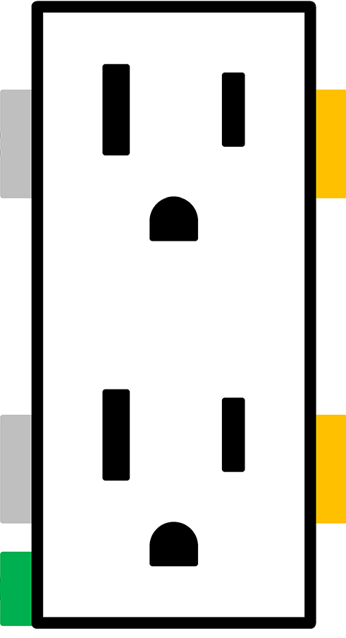
Pin Configuration and Descriptions
| Pin Name | Description |
|---|---|
| Line (Hot) | Carries the live current from the power supply. |
| Neutral | Completes the circuit by returning current to the power source. |
| Ground | Provides a safety path for fault currents to prevent electric shock. |
Usage Instructions
How to Use the Outlet in a Circuit
Wiring the Outlet:
- Connect the Line (Hot) wire to the terminal marked "L" or "Live."
- Connect the Neutral wire to the terminal marked "N" or "Neutral."
- Connect the Ground wire to the terminal marked with a ground symbol (⏚).
- Ensure all connections are secure and insulated to prevent short circuits.
Mounting the Outlet:
- Install the outlet into an electrical box that is securely fixed to the wall.
- Use screws to fasten the outlet cover plate for safety and aesthetics.
Testing the Outlet:
- Use a multimeter or outlet tester to verify proper wiring and functionality.
- Check for correct voltage between the Line and Neutral terminals.
Important Considerations and Best Practices
- Always turn off the power supply at the circuit breaker before installing or servicing an outlet.
- Use outlets rated for the specific voltage and current requirements of your devices.
- Avoid overloading the outlet by connecting too many high-power appliances simultaneously.
- For outdoor or wet locations, use weatherproof outlets with Ground Fault Circuit Interrupter (GFCI) protection.
- Regularly inspect outlets for signs of wear, damage, or overheating.
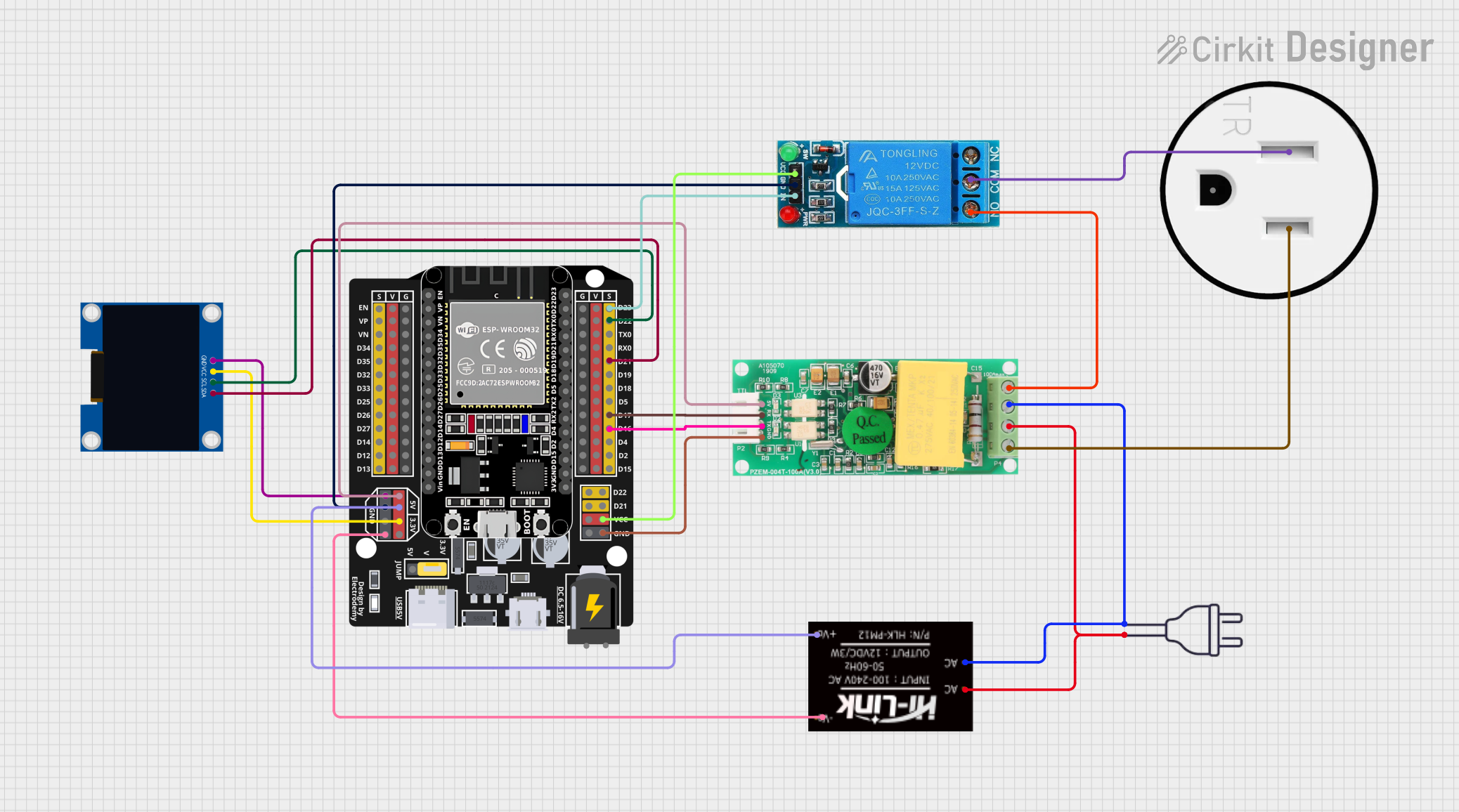
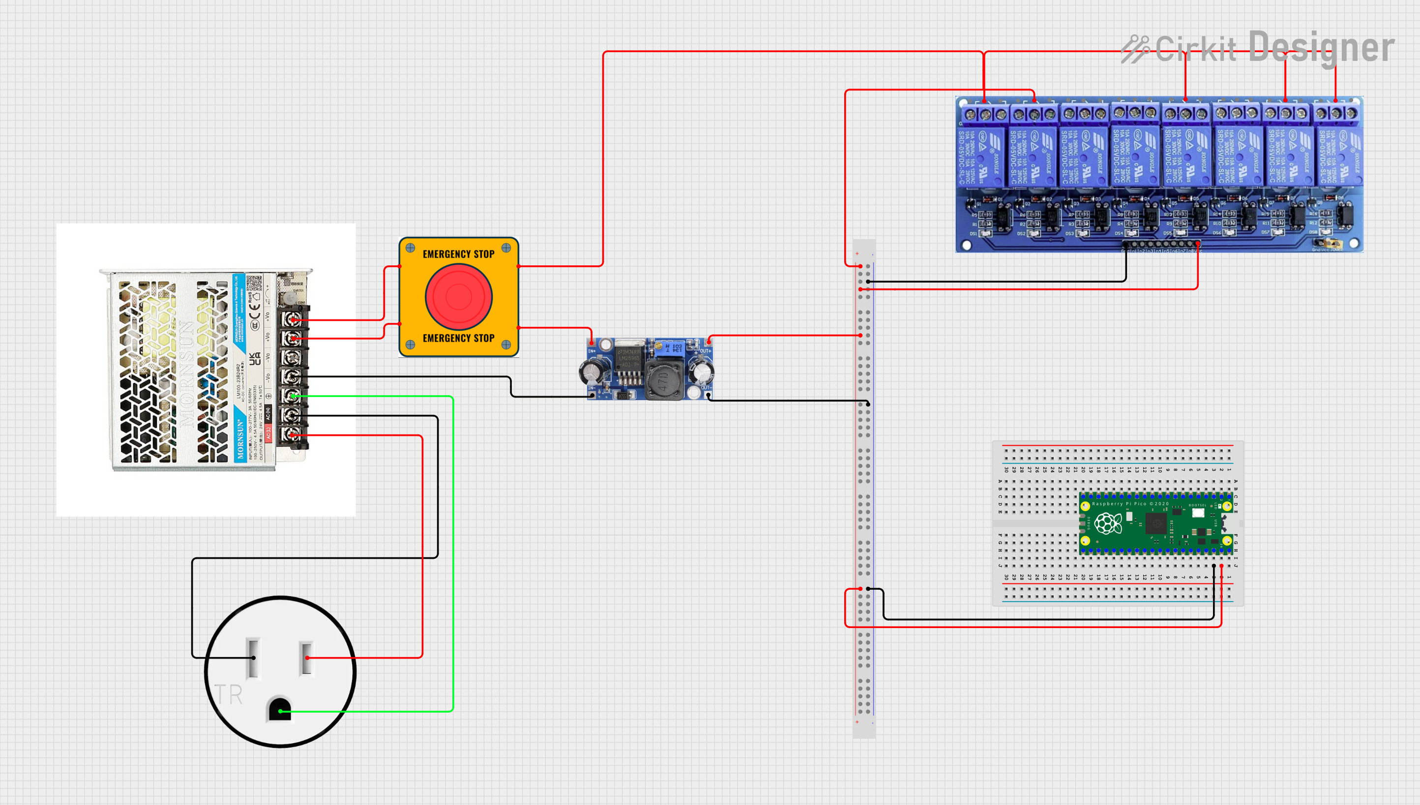
Example: Connecting an Outlet to an Arduino UNO
While outlets are not directly connected to an Arduino UNO, you can control an outlet using a relay module. Below is an example of how to control a lamp connected to an outlet using an Arduino:
/*
  Example: Controlling an Outlet with Arduino and a Relay Module
  This code turns a lamp connected to an outlet ON and OFF every 2 seconds.
  WARNING: Ensure proper isolation between high-voltage and low-voltage circuits.
*/

const int relayPin = 7; // Pin connected to the relay module

void setup() {
  pinMode(relayPin, OUTPUT); // Set relay pin as output
}

void loop() {
  digitalWrite(relayPin, HIGH); // Turn ON the relay (lamp ON)
  delay(2000);                 // Wait for 2 seconds
  digitalWrite(relayPin, LOW); // Turn OFF the relay (lamp OFF)
  delay(2000);                 // Wait for 2 seconds
}
Note: Always use a relay module with proper isolation to control high-voltage devices safely.
Troubleshooting and FAQs
Common Issues Users Might Face
Outlet Not Providing Power:
- Cause: Loose wiring or tripped circuit breaker.
- Solution: Check the wiring connections and reset the circuit breaker.
Overheating Outlet:
- Cause: Overloaded outlet or poor contact between plug and socket.
- Solution: Reduce the load on the outlet and inspect for damage.
Sparking When Plugging In Devices:
- Cause: Worn-out contacts or improper plug insertion.
- Solution: Replace the outlet if contacts are damaged and ensure proper plug alignment.
GFCI Outlet Keeps Tripping:
- Cause: Ground fault or moisture in the outlet.
- Solution: Inspect for water ingress and check connected devices for faults.
Solutions and Tips for Troubleshooting
- Use an outlet tester to quickly diagnose wiring issues.
- Replace old or damaged outlets to maintain safety and reliability.
- Consult a licensed electrician for complex installations or repairs.
- For smart outlets, ensure proper Wi-Fi connectivity and firmware updates.
By following this documentation, you can safely and effectively use outlets in your electrical projects and installations.