How to Use ESP-8266 Controller: Examples, Pinouts, and Specs
Introduction
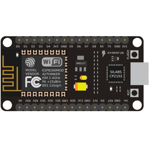
The ESP-8266 is a highly integrated Wi-Fi capable microcontroller that has gained immense popularity in the field of Internet of Things (IoT). Its low cost, compact design, and built-in Wi-Fi functionality make it an ideal choice for a wide range of applications, including home automation, sensor networks, and DIY projects.
Explore Projects Built with ESP-8266 Controller

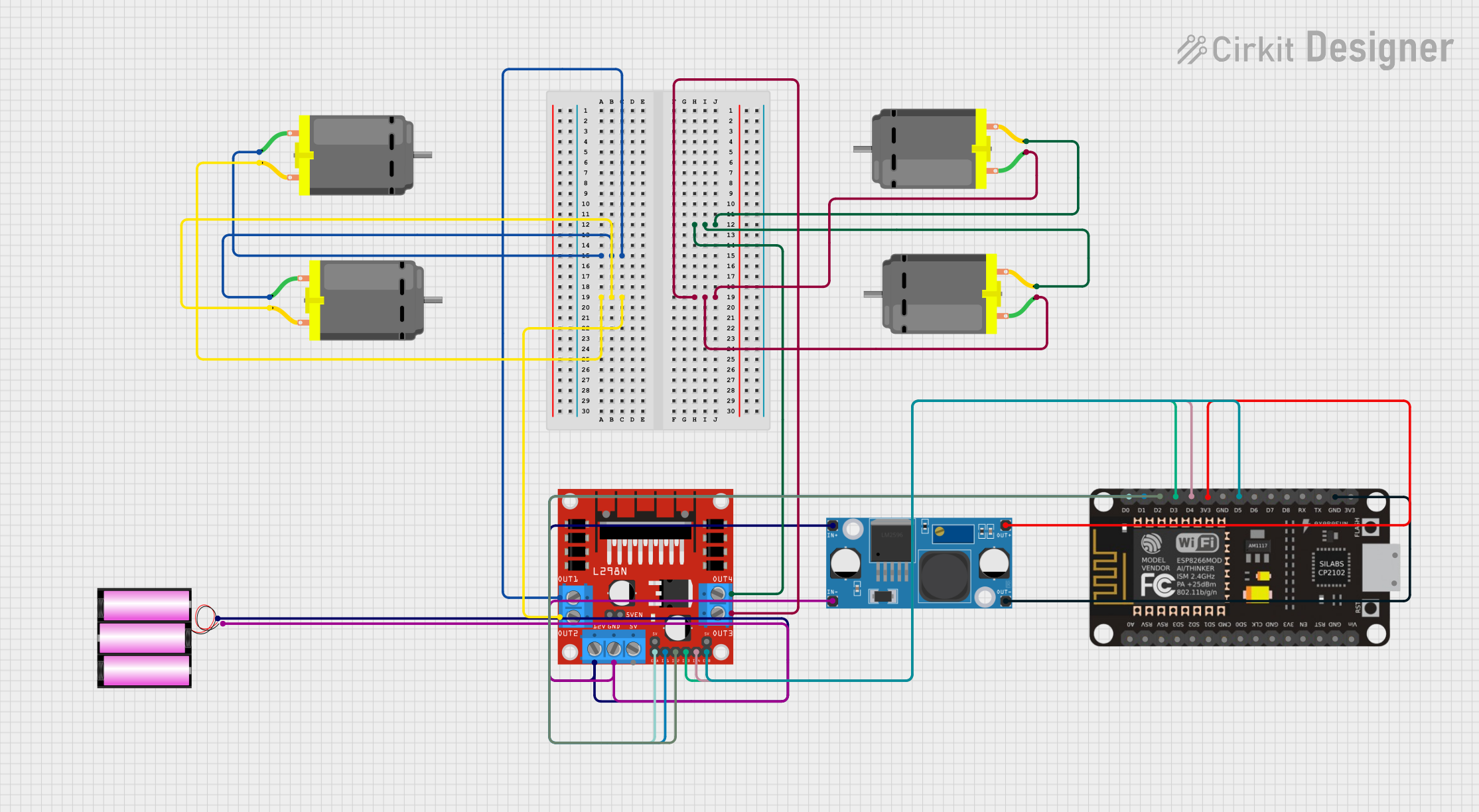
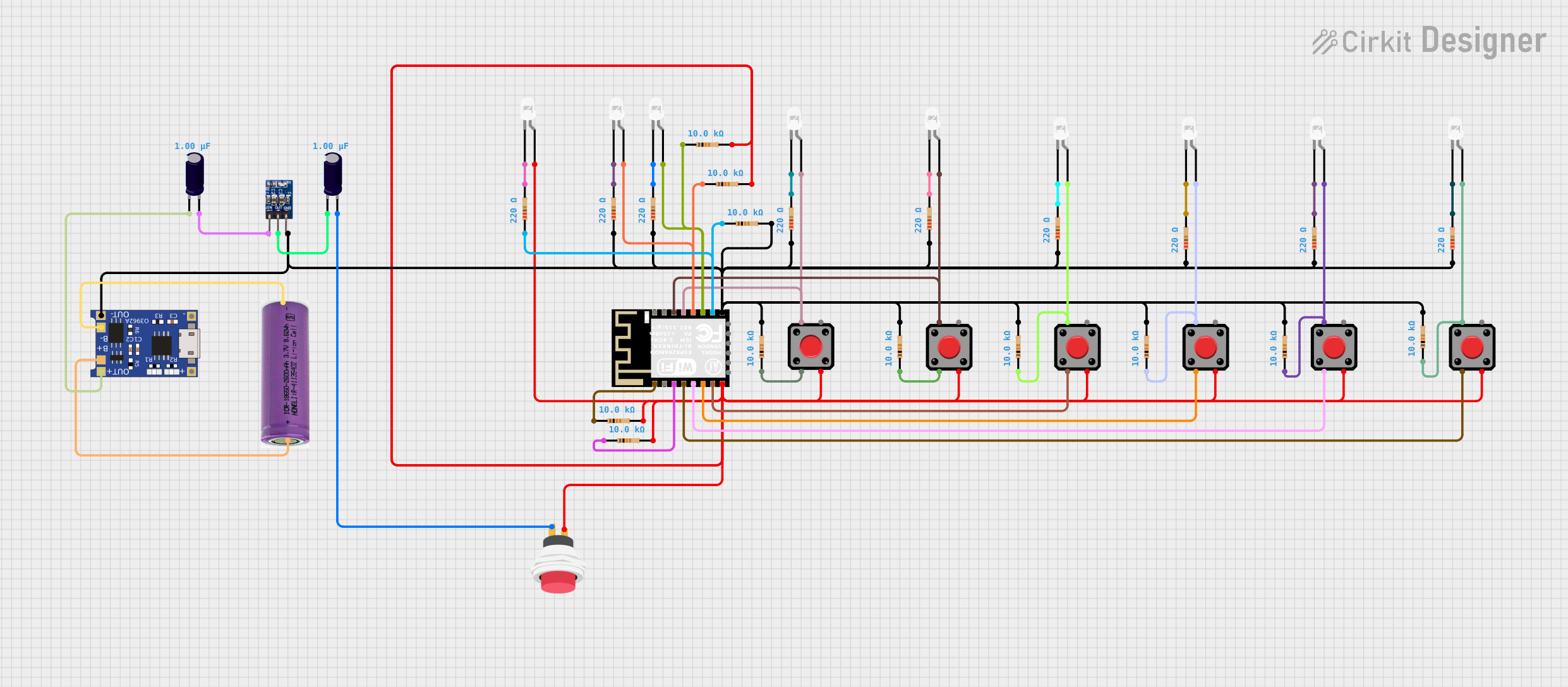
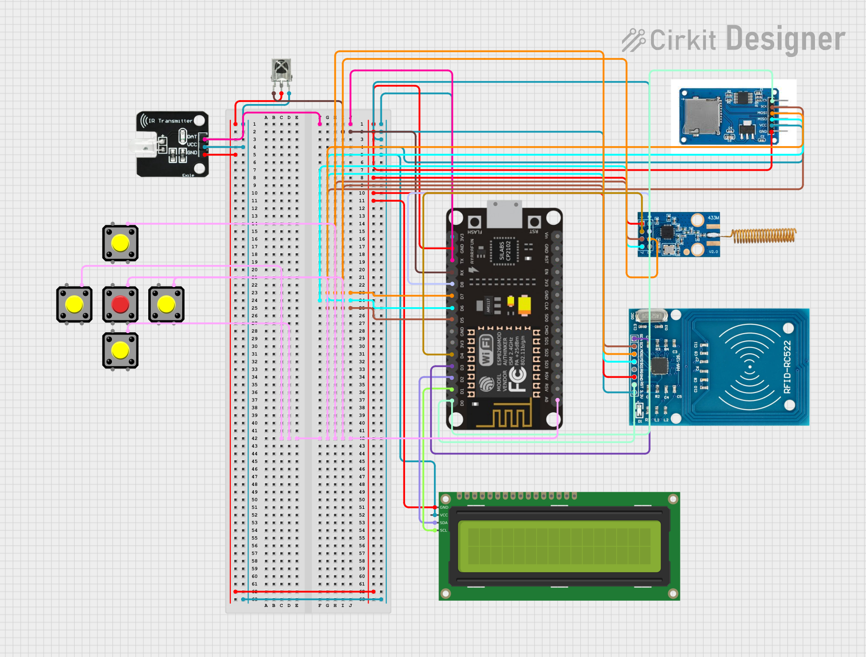
Explore Projects Built with ESP-8266 Controller
Common Applications and Use Cases
- Smart home devices
- Wireless sensor networks
- IoT prototypes
- Remote monitoring systems
Technical Specifications
Key Technical Details
- Operating Voltage: 3.0V to 3.6V
- Input Voltage (recommended): 3.3V
- Digital I/O Pins: 17
- Analog Input Pins: 1 (Max input: 1V)
- Wi-Fi Protocol: 802.11 b/g/n
- Frequency Range: 2.4 GHz - 2.5 GHz
- Flash Memory: Varies by model (e.g., 512KB to 4MB)
- DC Current per I/O Pin: 12 mA
Pin Configuration and Descriptions
| Pin Number | Name | Function |
|---|---|---|
| 1 | GND | Ground |
| 2 | GPIO2 | General Purpose Input/Output |
| 3 | GPIO0 | General Purpose Input/Output |
| ... | ... | ... |
| n | VCC | Power Supply (3.3V) |
Note: The pin configuration may vary slightly depending on the specific ESP-8266 module variant (e.g., ESP-01, ESP-12).
Usage Instructions
How to Use the Component in a Circuit
- Power Supply: Connect the VCC pin to a 3.3V power source and the GND pin to the ground.
- Programming: The ESP-8266 can be programmed using the Arduino IDE or other development environments. To enter programming mode, GPIO0 must be connected to GND during power-up.
- Wi-Fi Connection: Use the provided libraries to connect the ESP-8266 to a Wi-Fi network and communicate over the internet.
Important Considerations and Best Practices
- Voltage Levels: Ensure that the power supply does not exceed 3.6V to avoid damaging the module.
- Antenna: Keep the antenna area clear of metal components to ensure proper Wi-Fi signal reception.
- Heat Dissipation: Provide adequate cooling if the module is expected to operate at high temperatures or continuous Wi-Fi transmission.
Example Code for Arduino UNO
#include <ESP8266WiFi.h>

const char* ssid = "yourSSID"; // Replace with your Wi-Fi network name
const char* password = "yourPASSWORD"; // Replace with your Wi-Fi network password

void setup() {
  Serial.begin(115200);
  WiFi.begin(ssid, password);

  while (WiFi.status() != WL_CONNECTED) {
    delay(500);
    Serial.print(".");
  }

  Serial.println("");
  Serial.println("WiFi connected");
}

void loop() {
  // Your code here to run repeatedly
}
Note: This code snippet demonstrates how to connect the ESP-8266 to a Wi-Fi network. Make sure to replace yourSSID and yourPASSWORD with your actual Wi-Fi credentials.
Troubleshooting and FAQs
Common Issues
- Module Does Not Power On: Check the power supply and connections to ensure the module is receiving 3.3V.
- Cannot Connect to Wi-Fi: Verify the SSID and password are correct. Ensure the antenna is not obstructed.
- Unable to Program: Ensure GPIO0 is grounded when the module is powered on to enter programming mode.
Solutions and Tips for Troubleshooting
- Power Issues: Use a stable 3.3V power source capable of delivering sufficient current.
- Programming Issues: Double-check the wiring and ensure the correct board and port are selected in the IDE.
- Wi-Fi Connectivity: Move the module closer to the router or check for sources of Wi-Fi interference.
FAQs
Q: Can the ESP-8266 be powered directly from the Arduino UNO 3.3V pin?
A: It is not recommended as the UNO's 3.3V pin may not supply enough current for stable operation, especially during Wi-Fi transmission.
Q: How do I reset the ESP-8266?
A: Briefly connect the RST pin to GND or power cycle the module.
Q: Can the ESP-8266 operate in both station and access point modes?
A: Yes, the ESP-8266 can function as a Wi-Fi station, access point, or both simultaneously.
This documentation provides an overview of the ESP-8266 controller, its technical specifications, usage instructions, example code for Arduino UNO, and troubleshooting tips. For more detailed information, refer to the datasheet and technical references specific to the ESP-8266 module variant you are using.