How to Use DIALL 3 input: Examples, Pinouts, and Specs

Introduction
The DIALL 3 Input is a versatile digital input/output module designed for use in automation systems. It enables the connection and control of up to three input signals from sensors, switches, or other digital devices. This component is ideal for applications requiring reliable signal monitoring and processing in industrial, home automation, or robotics systems.
Explore Projects Built with DIALL 3 input


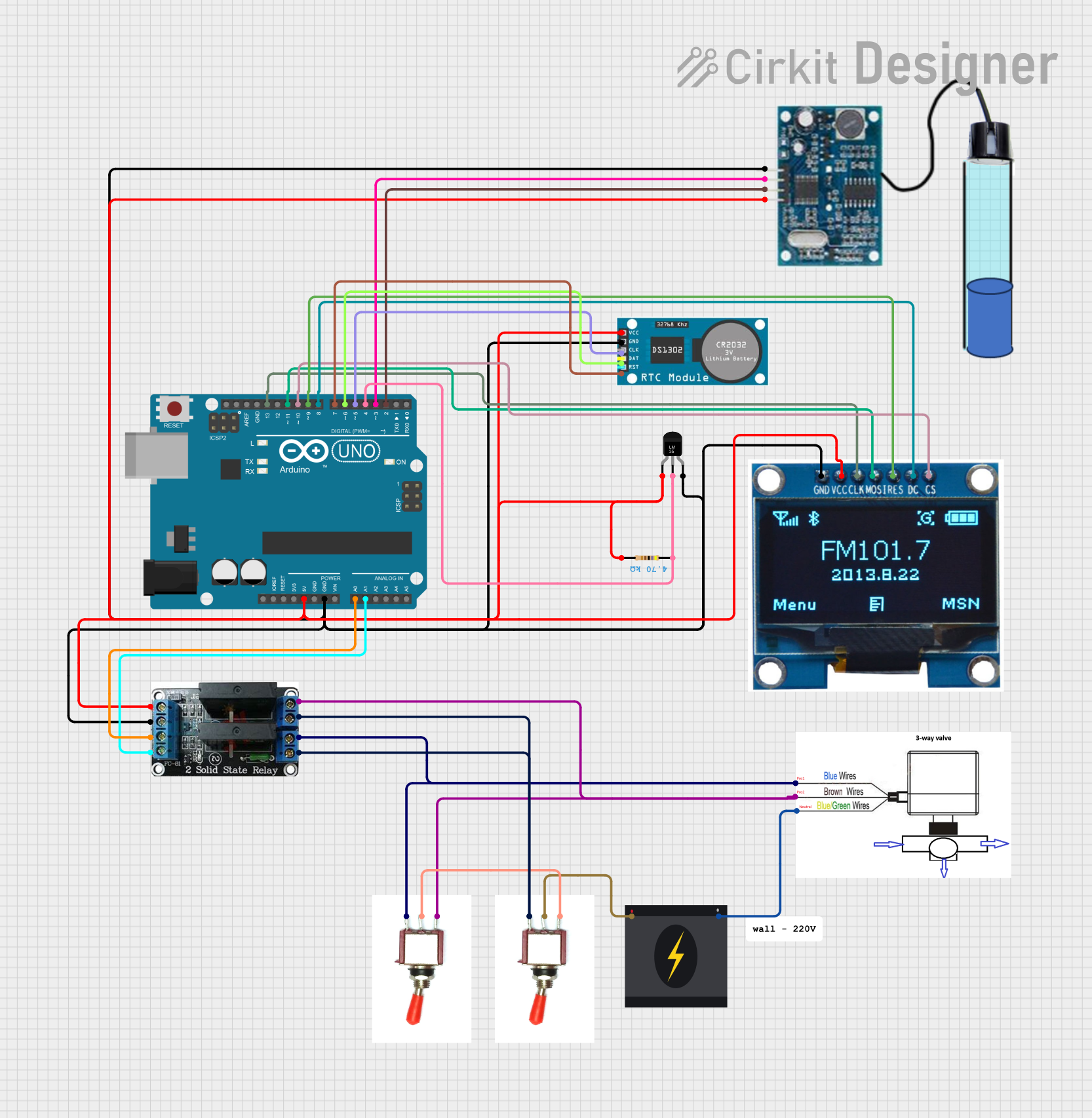
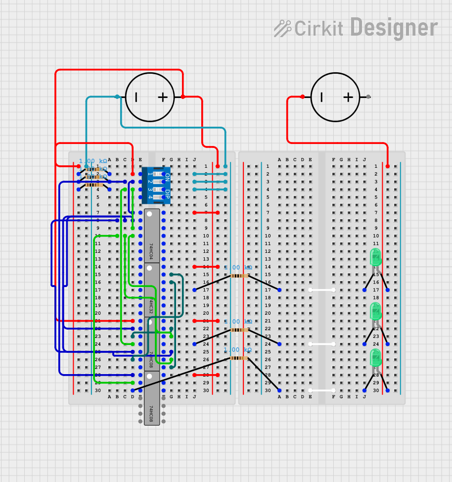
Explore Projects Built with DIALL 3 input
Common Applications and Use Cases
- Monitoring digital signals from sensors (e.g., proximity sensors, limit switches)
- Interfacing with control systems in industrial automation
- Home automation projects for detecting switch states
- Robotics systems for reading input signals from external devices
Technical Specifications
The DIALL 3 Input module is designed to operate efficiently in a variety of environments. Below are its key technical specifications:
| Parameter | Value |
|---|---|
| Operating Voltage | 5V DC |
| Input Voltage Range | 0V (LOW) to 5V (HIGH) |
| Input Channels | 3 |
| Input Impedance | 10 kΩ |
| Maximum Input Current | 10 mA per channel |
| Operating Temperature | -20°C to 70°C |
| Dimensions | 50mm x 30mm x 15mm |
Pin Configuration and Descriptions
The DIALL 3 Input module has a simple pinout for easy integration into circuits. Below is the pin configuration:
| Pin | Name | Description |
|---|---|---|
| 1 | VCC | Power supply input (5V DC) |
| 2 | GND | Ground connection |
| 3 | IN1 | Digital input channel 1 |
| 4 | IN2 | Digital input channel 2 |
| 5 | IN3 | Digital input channel 3 |
Usage Instructions
How to Use the DIALL 3 Input in a Circuit
- Power the Module: Connect the VCC pin to a 5V DC power source and the GND pin to the ground of your circuit.
- Connect Input Devices: Attach the output of your sensors, switches, or other digital devices to the IN1, IN2, and IN3 pins.
- Read Input Signals: Use a microcontroller (e.g., Arduino UNO) or other control systems to monitor the state of the input pins.
Important Considerations and Best Practices
- Ensure that the input voltage does not exceed 5V to prevent damage to the module.
- Use pull-down resistors if your input devices do not provide a stable LOW signal when inactive.
- Keep input wires as short as possible to minimize noise and interference.
- If using with an Arduino UNO, ensure the module shares a common ground with the Arduino.
Example Code for Arduino UNO
Below is an example Arduino sketch to read the input states of the DIALL 3 Input module:
// Define the input pins connected to the DIALL 3 module
const int inputPin1 = 2; // IN1 connected to Arduino digital pin 2
const int inputPin2 = 3; // IN2 connected to Arduino digital pin 3
const int inputPin3 = 4; // IN3 connected to Arduino digital pin 4

void setup() {
  // Initialize serial communication for debugging
  Serial.begin(9600);

  // Set the input pins as INPUT
  pinMode(inputPin1, INPUT);
  pinMode(inputPin2, INPUT);
  pinMode(inputPin3, INPUT);
}

void loop() {
  // Read the state of each input pin
  int state1 = digitalRead(inputPin1);
  int state2 = digitalRead(inputPin2);
  int state3 = digitalRead(inputPin3);

  // Print the states to the Serial Monitor
  Serial.print("IN1: ");
  Serial.print(state1);
  Serial.print(" | IN2: ");
  Serial.print(state2);
  Serial.print(" | IN3: ");
  Serial.println(state3);

  // Add a small delay to avoid flooding the Serial Monitor
  delay(500);
}
Troubleshooting and FAQs
Common Issues and Solutions
No Input Signal Detected
- Cause: The input device is not properly connected or powered.
- Solution: Verify the connections and ensure the input device is functioning correctly.
Incorrect Signal Readings
- Cause: Noise or interference in the input lines.
- Solution: Use shorter wires and add pull-down resistors if necessary.
Module Not Powering On
- Cause: Incorrect power supply voltage.
- Solution: Ensure the VCC pin is connected to a stable 5V DC source.
Arduino Not Reading Inputs
- Cause: Missing common ground between the DIALL 3 module and Arduino.
- Solution: Connect the GND pin of the module to the Arduino's GND pin.
FAQs
Q: Can the DIALL 3 Input module handle analog signals?
A: No, the DIALL 3 Input module is designed for digital signals only. Use an analog-to-digital converter (ADC) for analog signals.
Q: Can I use the DIALL 3 Input module with a 3.3V microcontroller?
A: Yes, but ensure the input signals do not exceed the voltage tolerance of your microcontroller.
Q: What happens if I connect more than 5V to an input pin?
A: Applying more than 5V can damage the module. Always ensure input signals are within the specified range.
Q: Can I use fewer than three input channels?
A: Yes, you can use only the channels you need. Leave unused input pins unconnected.