How to Use Dc-dc Lm2596 Step Down: Examples, Pinouts, and Specs
Introduction
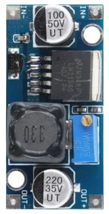
The LM2596 is a step-down (buck) voltage regulator designed to efficiently convert a higher input voltage to a lower output voltage. It is widely used in power supply applications due to its high efficiency, compact size, and ease of use. The LM2596 can handle up to 3A of output current and includes built-in thermal shutdown and current limiting for protection, making it a reliable choice for various electronic projects.
Explore Projects Built with Dc-dc Lm2596 Step Down


Explore Projects Built with Dc-dc Lm2596 Step Down
Common Applications and Use Cases
- Powering low-voltage devices from a higher voltage source (e.g., 12V to 5V conversion)
- Battery-powered systems
- Adjustable power supplies
- Embedded systems and microcontroller projects
- LED drivers
Technical Specifications
The LM2596 step-down regulator is available in both fixed and adjustable output voltage versions. Below are the key technical details:
Key Specifications
| Parameter | Value |
|---|---|
| Input Voltage Range | 4.5V to 40V |
| Output Voltage Range | 1.23V to 37V (adjustable version) |
| Output Current | Up to 3A |
| Efficiency | Up to 92% |
| Switching Frequency | 150 kHz |
| Output Voltage Tolerance | ±4% |
| Thermal Shutdown | Yes |
| Current Limiting | Yes |
Pin Configuration and Descriptions
The LM2596 is typically available in a 5-pin TO-220 package. Below is the pinout and description:
| Pin Number | Pin Name | Description |
|---|---|---|
| 1 | VIN | Input voltage (4.5V to 40V) |
| 2 | Output | Regulated output voltage |
| 3 | Ground (GND) | Ground connection |
| 4 | Feedback | Feedback pin for adjustable output voltage |
| 5 | ON/OFF | Enable/disable control (optional, not always used) |
Usage Instructions
How to Use the LM2596 in a Circuit
Connect the Input Voltage (VIN):
- Attach the positive terminal of the input voltage source to the VIN pin.
- Connect the negative terminal of the input source to the GND pin.
Set the Output Voltage (Adjustable Version):
- Use a voltage divider circuit with resistors connected to the Feedback pin to set the desired output voltage.
- The output voltage can be calculated using the formula:
[ V_{OUT} = V_{REF} \times \left(1 + \frac{R1}{R2}\right) ]
where ( V_{REF} ) is 1.23V, and ( R1 ) and ( R2 ) are the resistors in the voltage divider.
Connect the Load:
- Attach the positive terminal of the load to the Output pin.
- Connect the negative terminal of the load to the GND pin.
Optional ON/OFF Control:
- If the ON/OFF pin is available, it can be used to enable or disable the regulator.
- Connect the ON/OFF pin to GND to disable the regulator or leave it floating to enable it.
Add Input and Output Capacitors:
- Place a capacitor (e.g., 100µF) between VIN and GND to stabilize the input voltage.
- Place another capacitor (e.g., 100µF) between the Output pin and GND to reduce output voltage ripple.
Important Considerations and Best Practices
- Heat Dissipation: The LM2596 can generate heat during operation, especially at high currents. Use a heatsink or ensure proper ventilation to prevent overheating.
- Input Voltage: Ensure the input voltage is at least 1.5V higher than the desired output voltage for proper regulation.
- Output Ripple: Use low-ESR capacitors to minimize output voltage ripple.
- Inductor Selection: Choose an inductor with a current rating higher than the maximum output current to avoid saturation.
Example: Using LM2596 with Arduino UNO
The LM2596 can be used to power an Arduino UNO from a higher voltage source (e.g., a 12V battery). Below is an example circuit and code:
Circuit Connections
- Connect the 12V input to the VIN pin of the LM2596.
- Set the output voltage to 5V using the adjustable version of the LM2596.
- Connect the 5V output to the Arduino UNO's 5V pin and GND to GND.
Arduino Code Example
// Example code to blink an LED using Arduino UNO powered by LM2596
// Ensure the LM2596 output is set to 5V before connecting to Arduino

const int ledPin = 13; // Pin connected to the onboard LED

void setup() {
  pinMode(ledPin, OUTPUT); // Set the LED pin as an output
}

void loop() {
  digitalWrite(ledPin, HIGH); // Turn the LED on
  delay(1000);                // Wait for 1 second
  digitalWrite(ledPin, LOW);  // Turn the LED off
  delay(1000);                // Wait for 1 second
}
Troubleshooting and FAQs
Common Issues and Solutions
No Output Voltage:
- Check the input voltage; ensure it is within the specified range (4.5V to 40V).
- Verify all connections, especially VIN, GND, and Output.
- Ensure the ON/OFF pin is not grounded (if applicable).
Output Voltage is Incorrect:
- For the adjustable version, verify the resistor values in the voltage divider circuit.
- Check for loose connections or damaged components.
Excessive Heat:
- Ensure the input voltage is not excessively high compared to the output voltage.
- Use a heatsink or improve ventilation around the LM2596.
High Output Ripple:
- Add or replace the output capacitor with a low-ESR capacitor.
- Ensure proper grounding and minimize the length of wires in the circuit.
FAQs
Q: Can the LM2596 be used to power a Raspberry Pi?
A: Yes, the LM2596 can be used to power a Raspberry Pi. Ensure the output voltage is set to 5V and the current rating is sufficient for the Raspberry Pi model being used.
Q: What is the maximum current the LM2596 can handle?
A: The LM2596 can handle up to 3A of output current. However, proper heat dissipation is required at higher currents.
Q: Can I use the LM2596 with a solar panel?
A: Yes, the LM2596 can be used with a solar panel as long as the input voltage is within the specified range (4.5V to 40V).
Q: How do I reduce noise in the output voltage?
A: Use low-ESR capacitors, minimize wire lengths, and ensure proper grounding to reduce noise and ripple in the output voltage.