How to Use Flow Sensor: Examples, Pinouts, and Specs
Introduction
A flow sensor is a device designed to measure the flow rate of liquids or gases within a system. It provides real-time data that can be used for monitoring, control, and automation purposes. Flow sensors are widely used in various industries, including water management, HVAC systems, medical devices, and industrial automation. They are essential for ensuring accurate flow measurement and maintaining system efficiency.
Explore Projects Built with Flow Sensor
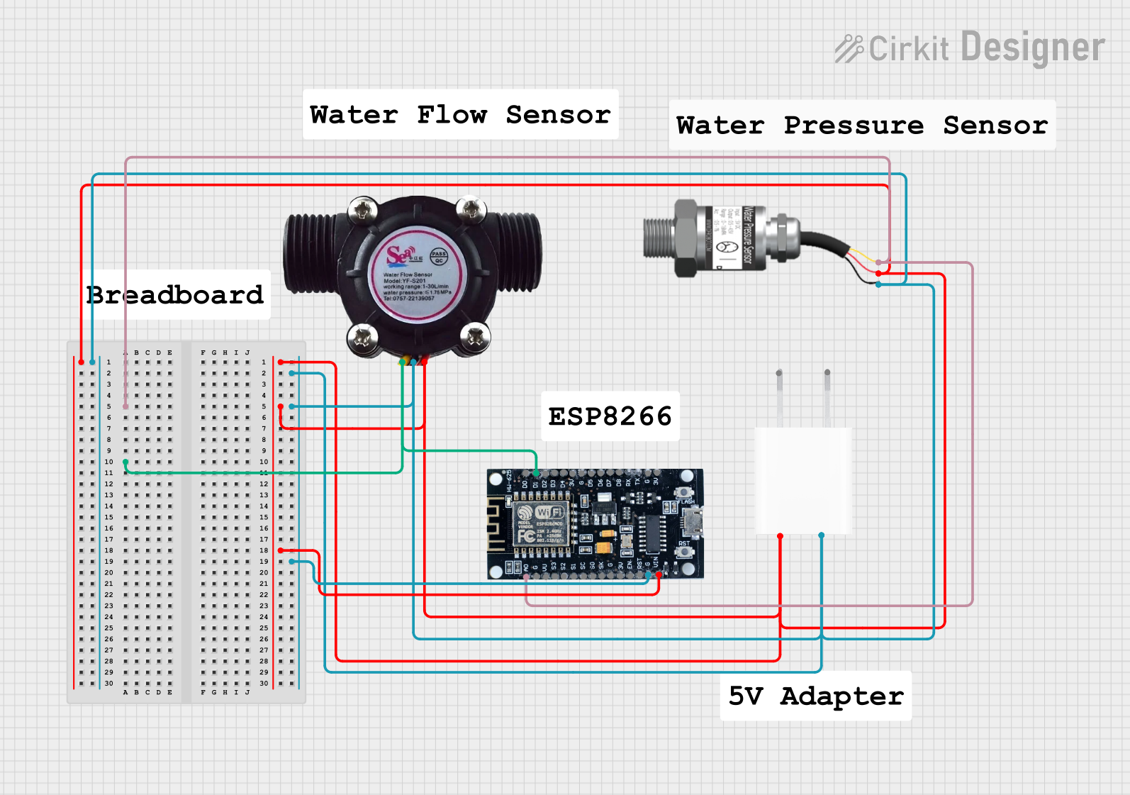
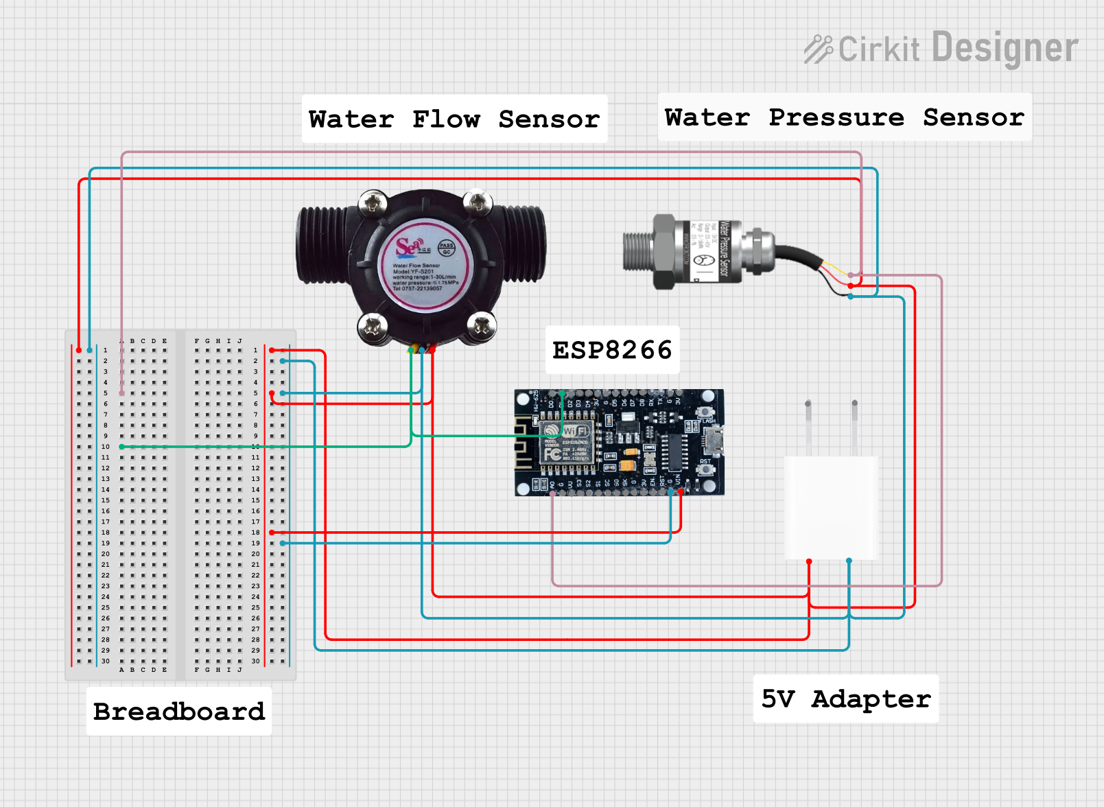
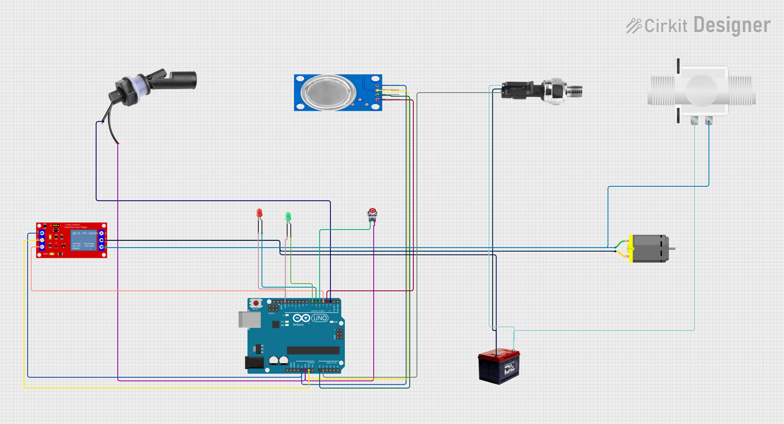
Explore Projects Built with Flow Sensor
Common Applications and Use Cases
- Water flow monitoring in irrigation systems and water distribution networks.
- Gas flow measurement in HVAC systems and industrial processes.
- Medical devices, such as ventilators and oxygen concentrators.
- Automotive applications, including fuel flow monitoring.
- Industrial automation for process control and optimization.
Technical Specifications
Below are the general technical specifications for a typical flow sensor. Note that specific models may vary, so always refer to the datasheet of your particular sensor.
Key Technical Details
- Operating Voltage: 5V to 24V DC (varies by model)
- Output Signal: Pulse signal (frequency proportional to flow rate)
- Flow Rate Range: 1 L/min to 30 L/min (typical for liquid sensors)
- Accuracy: ±1% to ±5% (depending on the model)
- Operating Temperature: -20°C to 85°C
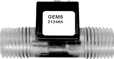
- Material: Plastic, brass, or stainless steel (depending on the application)
Pin Configuration and Descriptions
The pinout for a typical 3-pin flow sensor is as follows:
| Pin | Name | Description |
|---|---|---|
| 1 | VCC | Power supply input (typically 5V or 12V DC). |
| 2 | GND | Ground connection. |
| 3 | Signal (OUT) | Pulse output signal, where the frequency is proportional to the flow rate. |
Usage Instructions
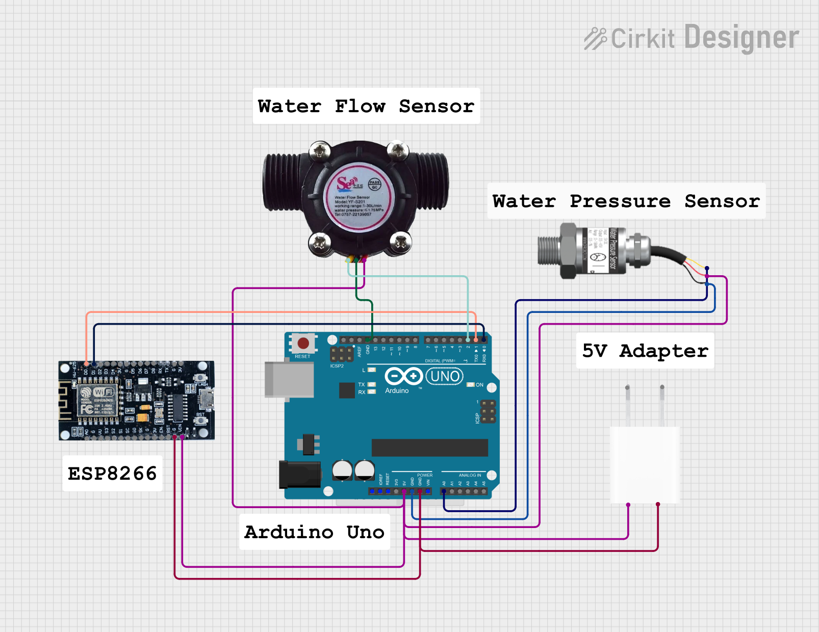
How to Use the Flow Sensor in a Circuit
- Power the Sensor: Connect the VCC pin to a 5V or 12V DC power source (as specified by your sensor model) and the GND pin to the ground of your circuit.
- Connect the Signal Pin: Attach the Signal (OUT) pin to a microcontroller's digital input pin (e.g., Arduino UNO pin D2).
- Read the Output: The sensor outputs a pulse signal, where the frequency corresponds to the flow rate. Use a microcontroller to count the pulses and calculate the flow rate.
Important Considerations and Best Practices
- Calibration: Always calibrate the sensor to ensure accurate measurements. The calibration factor (pulses per liter) is typically provided in the sensor's datasheet.
- Flow Direction: Ensure the sensor is installed in the correct orientation, as indicated by the arrow on the sensor body.
- Debris Protection: Use a filter upstream of the sensor to prevent debris from clogging or damaging the sensor.
- Avoid Air Bubbles: For liquid flow sensors, ensure the system is free of air bubbles, as they can affect accuracy.
- Power Supply: Use a stable power supply to avoid fluctuations in the sensor's output signal.
Example Code for Arduino UNO
Below is an example of how to interface a flow sensor with an Arduino UNO to measure and display the flow rate.
// Flow Sensor Example Code for Arduino UNO
// Measures and displays the flow rate in liters per minute (L/min)

const int flowSensorPin = 2; // Signal pin connected to Arduino digital pin 2
volatile int pulseCount = 0; // Variable to store pulse count

// Calibration factor (pulses per liter) - check your sensor's datasheet
const float calibrationFactor = 4.5;

unsigned long oldTime = 0; // To track time for flow rate calculation
float flowRate = 0;        // Flow rate in L/min

void setup() {
  pinMode(flowSensorPin, INPUT_PULLUP); // Set signal pin as input with pull-up
  attachInterrupt(digitalPinToInterrupt(flowSensorPin), countPulses, RISING);
  Serial.begin(9600); // Initialize serial communication
}

void loop() {
  unsigned long currentTime = millis();
  if (currentTime - oldTime > 1000) { // Calculate flow rate every second
    detachInterrupt(digitalPinToInterrupt(flowSensorPin)); // Disable interrupt
    flowRate = (pulseCount / calibrationFactor); // Calculate flow rate
    oldTime = currentTime; // Update time
    pulseCount = 0; // Reset pulse count
    Serial.print("Flow Rate: ");
    Serial.print(flowRate);
    Serial.println(" L/min");
    attachInterrupt(digitalPinToInterrupt(flowSensorPin), countPulses, RISING);
  }
}

// Interrupt service routine to count pulses
void countPulses() {
  pulseCount++;
}
Troubleshooting and FAQs
Common Issues and Solutions
No Output Signal
- Cause: Incorrect wiring or insufficient power supply.
- Solution: Double-check the wiring and ensure the power supply matches the sensor's requirements.
Inaccurate Flow Rate Readings
- Cause: Sensor not calibrated or air bubbles in the liquid.
- Solution: Calibrate the sensor using the calibration factor provided in the datasheet. Remove air bubbles from the system.
Sensor Not Responding
- Cause: Damaged sensor or clogged flow path.
- Solution: Inspect the sensor for physical damage or blockages. Clean or replace the sensor if necessary.
Fluctuating Readings
- Cause: Unstable power supply or electrical noise.
- Solution: Use a regulated power supply and ensure proper grounding. Add a capacitor across the power pins to filter noise.
FAQs
Q: Can I use a flow sensor with liquids other than water?
A: Yes, but ensure the sensor's material is compatible with the liquid to avoid corrosion or damage.Q: How do I determine the calibration factor for my sensor?
A: The calibration factor is typically provided in the sensor's datasheet. If unavailable, you can determine it experimentally by measuring the output pulses for a known flow rate.Q: Can I use a flow sensor with a 3.3V microcontroller?
A: Yes, but you may need a level shifter if the sensor operates at 5V. Alternatively, use a sensor designed for 3.3V operation.Q: What is the maximum flow rate my sensor can handle?
A: Refer to the sensor's datasheet for the maximum flow rate specification. Exceeding this limit may damage the sensor or result in inaccurate readings.