Cirkit Designer Logo
Cirkit Designer
Your all-in-one circuit design IDE
Home / 
Component Documentation

How to Use Automatic Buck-Boost Module 3.3V 2A / 5V 1A Output Regulated Power Supply Board TPS63802 Chip Lithium Battery Buck-Boost Control: Examples, Pinouts, and Specs

Image of Automatic Buck-Boost Module 3.3V 2A / 5V 1A Output Regulated Power Supply Board TPS63802 Chip Lithium Battery Buck-Boost Control
Cirkit Designer LogoDesign with Automatic Buck-Boost Module 3.3V 2A / 5V 1A Output Regulated Power Supply Board TPS63802 Chip Lithium Battery Buck-Boost Control in Cirkit Designer

Introduction

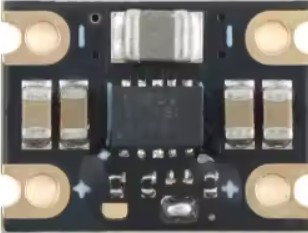
The Automatic Buck-Boost Module HL802A-3.3V, manufactured by Shenzhen Zheng Yi Electronic Technology Co., Ltd, is a versatile power supply module designed to regulate voltage levels efficiently. It can step down (buck) or step up (boost) input voltages to provide a stable output of either 3.3V at 2A or 5V at 1A. This module is powered by the TPS63802 chip, which ensures high efficiency and reliable performance, even in demanding applications.

Explore Projects Built with Automatic Buck-Boost Module 3.3V 2A / 5V 1A Output Regulated Power Supply Board TPS63802 Chip Lithium Battery Buck-Boost Control

Use Cirkit Designer to design, explore, and prototype these projects online. Some projects support real-time simulation. Click "Open Project" to start designing instantly!
Battery-Powered 18650 Li-ion Charger with USB Output and Adjustable Voltage Regulator
Image of Breadboard: A project utilizing Automatic Buck-Boost Module 3.3V 2A / 5V 1A Output Regulated Power Supply Board TPS63802 Chip Lithium Battery Buck-Boost Control in a practical application
This circuit is a battery management and power supply system that uses three 3.7V batteries connected to a 3S 10A Li-ion 18650 Charger Protection Board Module for balanced charging and protection. The system includes a TP4056 Battery Charging Protection Module for additional charging safety, a Step Up Boost Power Converter to regulate and boost the voltage, and a USB regulator to provide a stable 5V output, controlled by a push switch.
Cirkit Designer LogoOpen Project in Cirkit Designer
Battery-Powered Adjustable Voltage Regulator with Li-ion 18650 Batteries and BMS
Image of mini ups: A project utilizing Automatic Buck-Boost Module 3.3V 2A / 5V 1A Output Regulated Power Supply Board TPS63802 Chip Lithium Battery Buck-Boost Control in a practical application
This circuit is a power management system that uses four Li-ion 18650 batteries connected to a 2S 30A BMS for battery management and protection. The system includes step-up and step-down voltage regulators to provide adjustable output voltages, controlled by a rocker switch, and multiple DC jacks for power input and output.
Cirkit Designer LogoOpen Project in Cirkit Designer
Battery-Powered Lora G2 Node Station with 18650 Li-ion Batteries and Boost Converter
Image of Custom-Lora-G2-Node: A project utilizing Automatic Buck-Boost Module 3.3V 2A / 5V 1A Output Regulated Power Supply Board TPS63802 Chip Lithium Battery Buck-Boost Control in a practical application
This circuit is a portable power supply system that uses multiple 18650 Li-ion batteries to provide a stable 5V output through a boost converter. It includes a fast charging module with a USB-C input for recharging the batteries and a battery indicator for monitoring the battery status. The system powers a Lora G2 Node Station, making it suitable for wireless communication applications.
Cirkit Designer LogoOpen Project in Cirkit Designer
Battery-Powered Arduino UNO and ESP-8266 Smart Controller with LCD and RTC
Image of Ogie Diagram: A project utilizing Automatic Buck-Boost Module 3.3V 2A / 5V 1A Output Regulated Power Supply Board TPS63802 Chip Lithium Battery Buck-Boost Control in a practical application
This circuit is a power management and control system that uses a 12V power supply and a 18650 Li-ion battery pack to provide a stable 5V output through a step-down buck converter. It includes an Arduino UNO, an ESP-8266 controller, a DS1307 RTC module, and a 20x4 I2C LCD display for monitoring and control purposes. The ULN2003A breakout board is used for driving higher current loads.
Cirkit Designer LogoOpen Project in Cirkit Designer

Explore Projects Built with Automatic Buck-Boost Module 3.3V 2A / 5V 1A Output Regulated Power Supply Board TPS63802 Chip Lithium Battery Buck-Boost Control

Use Cirkit Designer to design, explore, and prototype these projects online. Some projects support real-time simulation. Click "Open Project" to start designing instantly!
Image of Breadboard: A project utilizing Automatic Buck-Boost Module 3.3V 2A / 5V 1A Output Regulated Power Supply Board TPS63802 Chip Lithium Battery Buck-Boost Control in a practical application
Battery-Powered 18650 Li-ion Charger with USB Output and Adjustable Voltage Regulator
This circuit is a battery management and power supply system that uses three 3.7V batteries connected to a 3S 10A Li-ion 18650 Charger Protection Board Module for balanced charging and protection. The system includes a TP4056 Battery Charging Protection Module for additional charging safety, a Step Up Boost Power Converter to regulate and boost the voltage, and a USB regulator to provide a stable 5V output, controlled by a push switch.
Cirkit Designer LogoOpen Project in Cirkit Designer
Image of mini ups: A project utilizing Automatic Buck-Boost Module 3.3V 2A / 5V 1A Output Regulated Power Supply Board TPS63802 Chip Lithium Battery Buck-Boost Control in a practical application
Battery-Powered Adjustable Voltage Regulator with Li-ion 18650 Batteries and BMS
This circuit is a power management system that uses four Li-ion 18650 batteries connected to a 2S 30A BMS for battery management and protection. The system includes step-up and step-down voltage regulators to provide adjustable output voltages, controlled by a rocker switch, and multiple DC jacks for power input and output.
Cirkit Designer LogoOpen Project in Cirkit Designer
Image of Custom-Lora-G2-Node: A project utilizing Automatic Buck-Boost Module 3.3V 2A / 5V 1A Output Regulated Power Supply Board TPS63802 Chip Lithium Battery Buck-Boost Control in a practical application
Battery-Powered Lora G2 Node Station with 18650 Li-ion Batteries and Boost Converter
This circuit is a portable power supply system that uses multiple 18650 Li-ion batteries to provide a stable 5V output through a boost converter. It includes a fast charging module with a USB-C input for recharging the batteries and a battery indicator for monitoring the battery status. The system powers a Lora G2 Node Station, making it suitable for wireless communication applications.
Cirkit Designer LogoOpen Project in Cirkit Designer
Image of Ogie Diagram: A project utilizing Automatic Buck-Boost Module 3.3V 2A / 5V 1A Output Regulated Power Supply Board TPS63802 Chip Lithium Battery Buck-Boost Control in a practical application
Battery-Powered Arduino UNO and ESP-8266 Smart Controller with LCD and RTC
This circuit is a power management and control system that uses a 12V power supply and a 18650 Li-ion battery pack to provide a stable 5V output through a step-down buck converter. It includes an Arduino UNO, an ESP-8266 controller, a DS1307 RTC module, and a 20x4 I2C LCD display for monitoring and control purposes. The ULN2003A breakout board is used for driving higher current loads.
Cirkit Designer LogoOpen Project in Cirkit Designer

Common Applications and Use Cases

  • Powering microcontrollers, sensors, and IoT devices from lithium-ion batteries.
  • Providing a stable voltage supply for portable electronics.
  • Applications requiring seamless transition between buck and boost modes.
  • Battery-powered systems where input voltage fluctuates above and below the desired output voltage.

Technical Specifications

Key Technical Details

Parameter Value
Input Voltage Range 1.8V to 5.5V
Output Voltage Options 3.3V (2A max) or 5V (1A max)
Output Current Up to 2A (3.3V mode) / Up to 1A (5V mode)
Efficiency Up to 95%
Chipset TPS63802
Operating Temperature Range -40°C to +85°C
Dimensions 22mm x 17mm x 4mm

Pin Configuration and Descriptions

Pin Name Pin Type Description
VIN Power Input Connect to the input voltage source (1.8V to 5.5V).
GND Ground Connect to the ground of the circuit.
VOUT Power Output Provides the regulated output voltage (3.3V or 5V).
EN Enable Input Active-high pin to enable the module. Pull low to disable the output.
SEL Voltage Select Selects the output voltage: High for 5V, Low for 3.3V.

Usage Instructions

How to Use the Component in a Circuit

  1. Connect the Input Voltage:

    • Attach the input voltage source (e.g., a lithium-ion battery) to the VIN pin.
    • Ensure the input voltage is within the range of 1.8V to 5.5V.
  2. Set the Output Voltage:

    • Use the SEL pin to select the desired output voltage:
      • Pull SEL high (connect to VIN) for a 5V output.
      • Pull SEL low (connect to GND) for a 3.3V output.
  3. Enable the Module:

    • Pull the EN pin high to enable the module.
    • To disable the output, pull the EN pin low.
  4. Connect the Load:

    • Attach the load to the VOUT pin and ensure the current draw does not exceed the module's limits (2A for 3.3V or 1A for 5V).
  5. Ground Connections:

    • Connect the GND pin to the ground of the input source and the load.

Important Considerations and Best Practices

  • Input Voltage Range: Ensure the input voltage remains within the specified range (1.8V to 5.5V) to avoid damage to the module.
  • Heat Dissipation: For high current loads, ensure adequate ventilation or heat sinking to prevent overheating.
  • Capacitor Placement: Place decoupling capacitors close to the input and output pins to minimize noise and improve stability.
  • SEL Pin Configuration: Avoid leaving the SEL pin floating; always connect it to either VIN or GND.

Example: Using the Module with an Arduino UNO

The following example demonstrates how to use the module to power an Arduino UNO with a 5V output.

Circuit Connections

  • Connect the module's VIN pin to a 3.7V lithium-ion battery.
  • Connect the VOUT pin to the Arduino UNO's 5V pin.
  • Connect the GND pin to the Arduino UNO's GND pin.
  • Pull the SEL pin high to set the output voltage to 5V.
  • Pull the EN pin high to enable the module.

Arduino Code Example

// Example code to monitor the Arduino's input voltage using the Automatic Buck-Boost Module
// Ensure the module is set to 5V output mode (SEL pin high).

void setup() {
  Serial.begin(9600); // Initialize serial communication at 9600 baud
  pinMode(A0, INPUT); // Configure analog pin A0 to read input voltage
}

void loop() {
  int sensorValue = analogRead(A0); // Read the analog input
  float voltage = sensorValue * (5.0 / 1023.0); // Convert to voltage (5V reference)
  
  // Print the voltage to the Serial Monitor
  Serial.print("Input Voltage: ");
  Serial.print(voltage);
  Serial.println(" V");
  
  delay(1000); // Wait for 1 second before the next reading
}

Troubleshooting and FAQs

Common Issues and Solutions

Issue Possible Cause Solution
No output voltage EN pin is not pulled high Ensure the EN pin is connected to VIN or a high logic level.
Incorrect output voltage SEL pin is not configured correctly Verify the SEL pin is connected to VIN for 5V or GND for 3.3V.
Overheating during operation Excessive load current Reduce the load current or improve heat dissipation.
Module not functioning with input below 3V Input voltage too low for operation Ensure the input voltage is within the specified range (1.8V to 5.5V).

FAQs

  1. Can this module be used with a 9V battery?

    • No, the input voltage range is limited to 1.8V to 5.5V. A 9V battery exceeds this range and may damage the module.
  2. What happens if the load exceeds the current limit?

    • The module may enter thermal shutdown or reduce efficiency. Always ensure the load current is within the specified limits.
  3. Is the module suitable for powering Raspberry Pi boards?

    • The module can power Raspberry Pi boards that require 5V, but ensure the current demand does not exceed 1A.
  4. Can I leave the SEL pin floating?

    • No, the SEL pin must be explicitly connected to either VIN (for 5V) or GND (for 3.3V) to ensure proper operation.

By following this documentation, users can effectively integrate the HL802A-3.3V Automatic Buck-Boost Module into their projects for reliable and efficient power management.