How to Use IRFZ44N: Examples, Pinouts, and Specs
Introduction
The IRFZ44N is an N-channel MOSFET (Metal-Oxide-Semiconductor Field-Effect Transistor) designed for high-speed switching applications. It is widely used in circuits requiring efficient power management, motor control, and switching operations. With its low on-resistance, high current capacity, and ability to handle voltages up to 55V, the IRFZ44N is a versatile and reliable component for various electronic projects.
Explore Projects Built with IRFZ44N


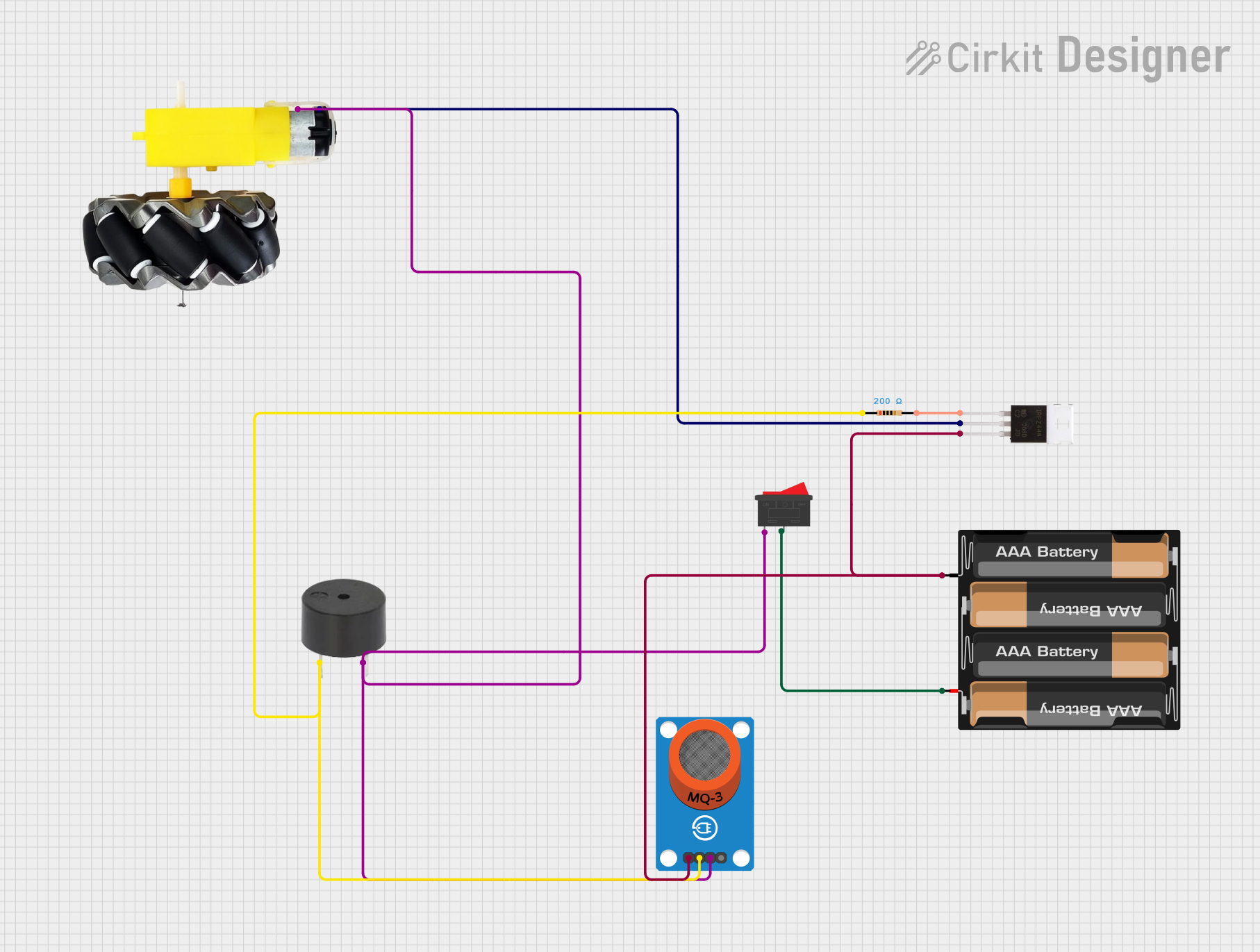
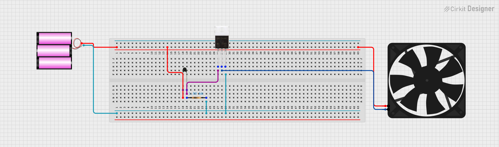
Explore Projects Built with IRFZ44N
Common Applications
- DC motor control in robotics and automation
- Switching power supplies and converters
- LED dimming and lighting control
- Battery management systems
- High-speed switching in industrial equipment
Technical Specifications
Key Specifications
| Parameter | Value |
|---|---|
| Type | N-Channel MOSFET |
| Maximum Drain-Source Voltage (VDS) | 55V |
| Maximum Gate-Source Voltage (VGS) | ±20V |
| Continuous Drain Current (ID) | 49A (at 25°C) |
| Pulsed Drain Current (IDM) | 160A |
| Power Dissipation (PD) | 94W |
| On-Resistance (RDS(on)) | 17.5 mΩ (at VGS = 10V) |
| Gate Threshold Voltage (VGS(th)) | 2.0V - 4.0V |
| Operating Temperature Range | -55°C to +175°C |
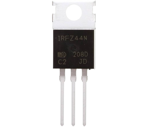
| Package Type | TO-220 |
Pin Configuration
The IRFZ44N is housed in a TO-220 package with three pins. The pinout is as follows:
| Pin Number | Pin Name | Description |
|---|---|---|
| 1 | Gate | Controls the MOSFET switching state |
| 2 | Drain | Current flows from drain to source |
| 3 | Source | Connected to ground or load return |
Usage Instructions
How to Use the IRFZ44N in a Circuit
- Gate Control: Apply a voltage to the Gate (Pin 1) to control the MOSFET. A voltage of 10V is typically recommended for full switching.
- Drain-Source Connection: Connect the load between the Drain (Pin 2) and the positive supply voltage. The Source (Pin 3) is usually connected to ground.
- Gate Resistor: Use a resistor (e.g., 10Ω) between the Gate and the control signal to limit inrush current and prevent damage to the MOSFET.
- Flyback Diode: When driving inductive loads (e.g., motors), add a flyback diode across the load to protect the MOSFET from voltage spikes.
Example Circuit with Arduino UNO
The IRFZ44N can be used to control a DC motor with an Arduino UNO. Below is an example circuit and code:
Circuit Connections
- Gate (Pin 1): Connect to an Arduino digital pin (e.g., D9) through a 10Ω resistor.
- Drain (Pin 2): Connect to one terminal of the motor.
- Source (Pin 3): Connect to ground.
- Motor: Connect the other terminal to the positive supply voltage.
- Flyback Diode: Place a diode (e.g., 1N4007) across the motor terminals, with the cathode connected to the positive supply.
Arduino Code
// IRFZ44N MOSFET Motor Control Example
// This code demonstrates how to control a DC motor using PWM signals.

const int motorPin = 9; // Pin connected to the Gate of the IRFZ44N

void setup() {
  pinMode(motorPin, OUTPUT); // Set the motor pin as an output
}

void loop() {
  // Gradually increase motor speed
  for (int speed = 0; speed <= 255; speed++) {
    analogWrite(motorPin, speed); // Write PWM signal to the Gate
    delay(10); // Small delay for smooth acceleration
  }

  // Gradually decrease motor speed
  for (int speed = 255; speed >= 0; speed--) {
    analogWrite(motorPin, speed); // Write PWM signal to the Gate
    delay(10); // Small delay for smooth deceleration
  }
}
Important Considerations
- Ensure the Gate-Source voltage (VGS) does not exceed ±20V to avoid damaging the MOSFET.
- Use a heatsink if the MOSFET is expected to handle high currents to prevent overheating.
- Verify the power dissipation and ensure it is within the specified limits (94W max).
Troubleshooting and FAQs
Common Issues and Solutions
MOSFET Not Switching Properly
- Cause: Insufficient Gate voltage.
- Solution: Ensure the Gate voltage is at least 10V for full switching.
Overheating
- Cause: High current or inadequate cooling.
- Solution: Use a heatsink and ensure proper ventilation.
Motor Not Running
- Cause: Incorrect wiring or damaged MOSFET.
- Solution: Double-check connections and test the MOSFET with a multimeter.
Voltage Spikes
- Cause: Inductive load without a flyback diode.
- Solution: Add a flyback diode across the load.
FAQs
Q: Can the IRFZ44N be used with 3.3V logic?
A: The IRFZ44N requires a Gate voltage of at least 10V for full switching. For 3.3V logic, consider using a logic-level MOSFET like the IRLZ44N.
Q: What is the maximum current the IRFZ44N can handle?
A: The IRFZ44N can handle up to 49A continuously at 25°C, but proper cooling is required to avoid overheating.
Q: Do I need a resistor on the Gate?
A: Yes, a resistor (e.g., 10Ω) is recommended to limit inrush current and protect the MOSFET.
Q: Can I use the IRFZ44N for AC loads?
A: The IRFZ44N is designed for DC applications. For AC loads, consider using a TRIAC or other suitable components.