How to Use AMC1400EVM: Examples, Pinouts, and Specs
AMC1400EVM Documentation
1. Introduction
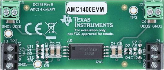
The AMC1400EVM is an evaluation module designed by Texas Instruments to facilitate the testing and evaluation of the AMC1400, a precision isolated amplifier. The AMC1400 is engineered for high-performance applications requiring accurate signal isolation, low noise, and high linearity. This evaluation module provides a convenient platform for engineers and developers to explore the capabilities of the AMC1400 in various use cases.
Key Features:
- High-precision isolated amplifier with ±250 mV input range.
- High common-mode transient immunity (CMTI) of 15 kV/µs (typical).
- Low offset drift and high linearity for accurate signal processing.
- Galvanic isolation for safety-critical applications.
Common Applications:
- Industrial Automation: Motor control, current sensing, and power monitoring.
- Medical Equipment: Patient monitoring and diagnostic devices.
- Renewable Energy Systems: Solar inverters and battery management systems.
- Test and Measurement Equipment: High-precision signal acquisition.
2. Technical Specifications
The following table outlines the key technical specifications of the AMC1400EVM:
| Parameter | Value |
|---|---|
| Input Voltage Range | ±250 mV |
| Output Voltage Range | 0.5 V to 4.5 V |
| Supply Voltage (VDD1) | 3.0 V to 5.5 V |
| Supply Voltage (VDD2) | 3.0 V to 5.5 V |
| Isolation Voltage | 5 kV RMS |
| Common-Mode Transient Immunity (CMTI) | 15 kV/µs (typical) |
| Operating Temperature Range | -40°C to +125°C |
| Package Type | SOIC-8 (AMC1400) |
Pin Configuration and Descriptions
The AMC1400EVM provides access to the AMC1400's pins via test points and connectors. Below is the pin configuration for the AMC1400:
| Pin | Name | Description |
|---|---|---|
| 1 | VIN+ | Non-inverting analog input (connect to the positive side of the input signal). |
| 2 | VIN- | Inverting analog input (connect to the negative side of the input signal). |
| 3 | GND1 | Ground reference for the input side. |
| 4 | VDD1 | Power supply for the input side (3.0 V to 5.5 V). |
| 5 | GND2 | Ground reference for the output side. |
| 6 | VOUT | Analog output signal (proportional to the input signal). |
| 7 | REFOUT | Reference voltage output (typically 2.5 V). |
| 8 | VDD2 | Power supply for the output side (3.0 V to 5.5 V). |
3. Usage Instructions
Connecting the AMC1400EVM to a Circuit
Power Supply:
- Connect a regulated power supply to the
VDD1andVDD2pins. - Ensure both sides are powered within the range of 3.0 V to 5.5 V.
- Connect
GND1andGND2to their respective ground references.
- Connect a regulated power supply to the
Input Signal:
- Apply the differential input signal to the
VIN+andVIN-pins. - Ensure the input signal does not exceed the ±250 mV range.
- Apply the differential input signal to the
Output Signal:
- Measure the output signal at the
VOUTpin. - The output voltage will be proportional to the input signal, scaled by the internal gain.
- Measure the output signal at the
Reference Voltage:
- Use the
REFOUTpin to access the internal reference voltage (2.5 V typical).
- Use the
Important Considerations:
- Isolation: The AMC1400 provides galvanic isolation between the input and output sides. Ensure proper grounding to maintain isolation integrity.
- Input Signal Conditioning: Use appropriate filtering or signal conditioning to prevent noise from affecting the input signal.
- Thermal Management: Operate the module within the specified temperature range (-40°C to +125°C) to ensure reliable performance.
4. Example Application with Arduino UNO
The AMC1400EVM can be interfaced with an Arduino UNO for signal acquisition and processing. Below is an example of how to read the output signal from the AMC1400EVM using the Arduino's ADC.
Circuit Diagram:
- Connect
VOUTfrom the AMC1400EVM to an analog input pin (e.g., A0) on the Arduino UNO. - Power the AMC1400EVM using a 5 V supply from the Arduino's
5VandGNDpins.
Arduino Code:
// AMC1400EVM Example with Arduino UNO
// Reads the output voltage from the AMC1400EVM and displays it via Serial Monitor.

const int analogPin = A0; // Analog pin connected to VOUT of AMC1400EVM
const float referenceVoltage = 5.0; // Arduino UNO reference voltage (5V)
const int adcResolution = 1024; // 10-bit ADC resolution (0-1023)

void setup() {
  Serial.begin(9600); // Initialize serial communication at 9600 baud
  pinMode(analogPin, INPUT); // Set the analog pin as input
}

void loop() {
  int adcValue = analogRead(analogPin); // Read the ADC value
  float outputVoltage = (adcValue * referenceVoltage) / adcResolution;
  // Convert ADC value to voltage

  Serial.print("Output Voltage: ");
  Serial.print(outputVoltage, 3); // Print voltage with 3 decimal places
  Serial.println(" V");

  delay(500); // Wait for 500 ms before the next reading
}
Notes:
- Ensure the Arduino's ADC reference voltage matches the
VDD2supply voltage of the AMC1400EVM. - Use a voltage divider or level shifter if the output voltage exceeds the Arduino's ADC range.
5. Troubleshooting and FAQs
Common Issues and Solutions
| Issue | Possible Cause | Solution |
|---|---|---|
No output signal at VOUT. |
Power supply not connected or incorrect. | Verify VDD1 and VDD2 connections and ensure proper voltage levels. |
| Output signal is noisy or unstable. | Input signal is noisy or improperly grounded. | Use proper filtering and ensure correct grounding on both sides. |
| Output voltage exceeds expected range. | Input signal exceeds ±250 mV range. | Ensure the input signal is within the specified range. |
| Arduino reads incorrect voltage. | Mismatch in reference voltage or wiring. | Verify the Arduino's reference voltage and check all connections. |
Frequently Asked Questions (FAQs)
Can the AMC1400EVM be used with a 3.3 V system?
- Yes, the AMC1400EVM supports supply voltages as low as 3.0 V, making it compatible with 3.3 V systems.
What is the purpose of the
REFOUTpin?- The
REFOUTpin provides a stable 2.5 V reference voltage, which can be used for external circuits or as a reference for ADCs.
- The
How do I ensure proper isolation?
- Maintain separate ground planes for
GND1andGND2. Avoid connecting them directly to preserve isolation.
- Maintain separate ground planes for
Can the AMC1400EVM measure AC signals?
- Yes, the AMC1400EVM can measure AC signals within the ±250 mV input range.
This documentation provides a comprehensive guide to using the AMC1400EVM. For further details, refer to the official Texas Instruments AMC1400EVM User Guide.
Explore Projects Built with AMC1400EVM


Explore Projects Built with AMC1400EVM