
How to Use 23LCV1024: Examples, Pinouts, and Specs
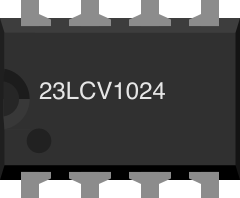
 Design with 23LCV1024 in Cirkit Designer
Introduction
The 23LCV1024 is a 1 Mbit (128K x 8) serial SRAM manufactured by Microchip Technology. It is designed for high-speed data storage and retrieval in embedded systems. The component operates using an SPI (Serial Peripheral Interface) protocol, which ensures efficient communication with microcontrollers and other digital devices. With its low power consumption and fast access times, the 23LCV1024 is ideal for applications requiring quick and reliable data processing.
Explore Projects Built with 23LCV1024
 Open Project in Cirkit Designer
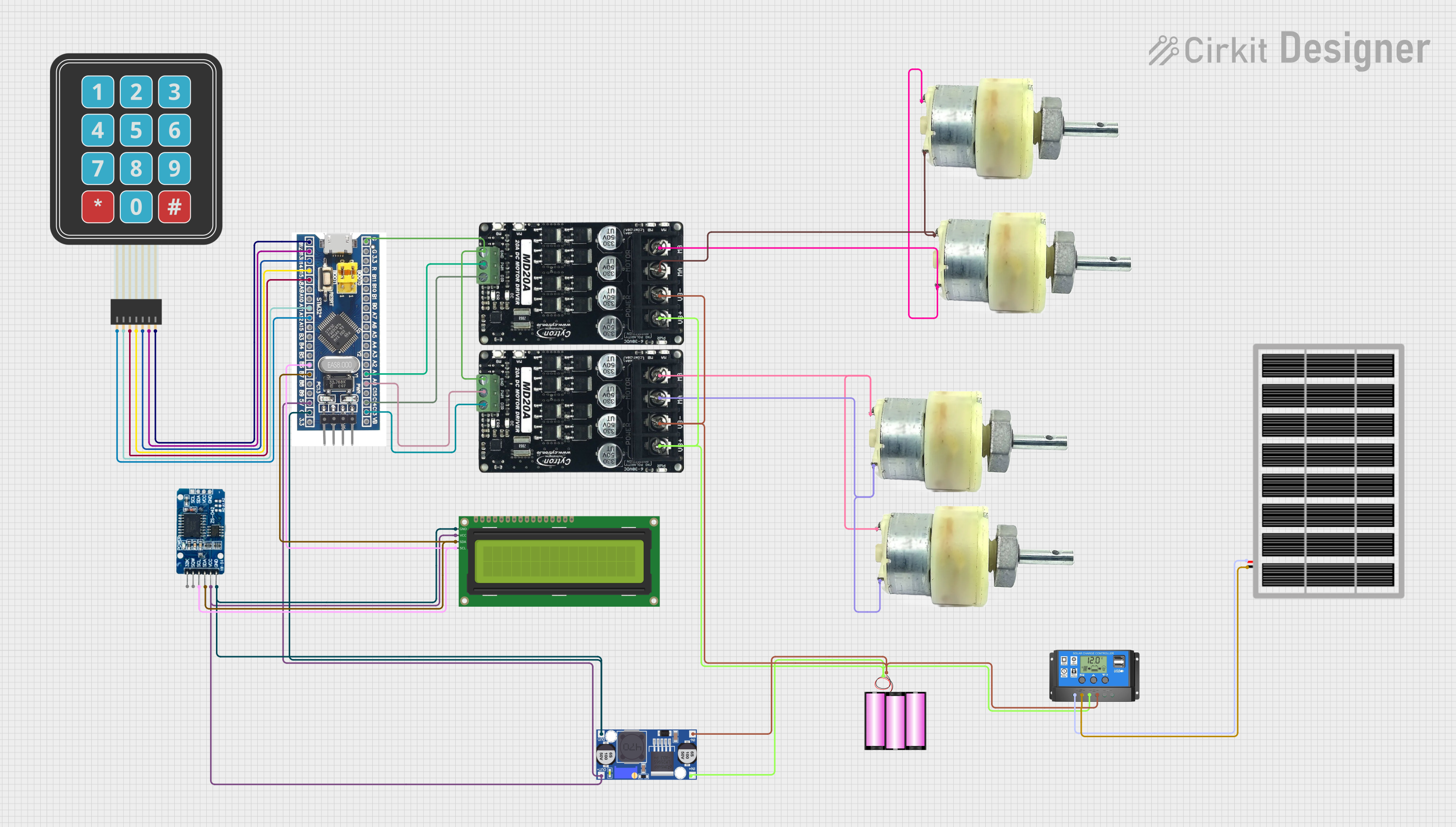 Open Project in Cirkit Designer
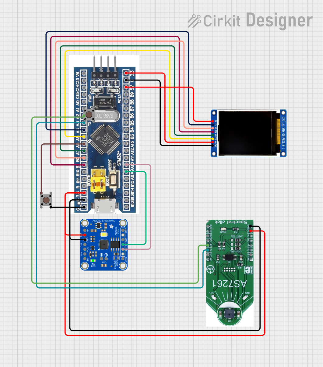 Open Project in Cirkit Designer
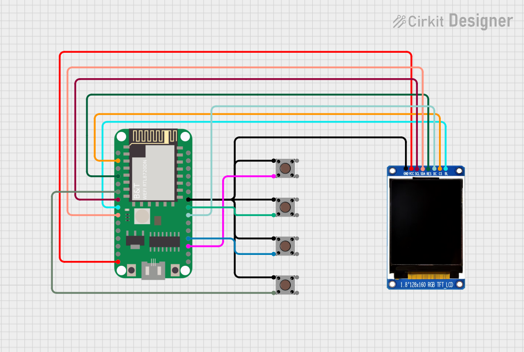 Open Project in Cirkit Designer
Explore Projects Built with 23LCV1024
Open Project in Cirkit DesignerOpen Project in Cirkit DesignerOpen Project in Cirkit DesignerOpen Project in Cirkit DesignerCommon Applications
- Data buffering in embedded systems
- High-speed temporary data storage
- Video frame buffering
- Audio data processing
- Industrial control systems
- IoT devices requiring low-power memory solutions
Technical Specifications
Key Technical Details
| Parameter | Value |
|---|---|
| Memory Size | 1 Mbit (128K x 8) |
| Interface | SPI (Serial Peripheral Interface) |
| Operating Voltage Range | 2.5V to 5.5V |
| Standby Current | 4 µA (typical) |
| Operating Current | 3 mA (typical at 1 MHz, 3.6V) |
| Maximum Clock Frequency | 20 MHz |
| Data Retention | > 200 years |
| Package Options | 8-pin SOIC, PDIP, or TSSOP |
| Temperature Range | -40°C to +85°C (Industrial Grade) |
Pin Configuration and Descriptions
The 23LCV1024 is available in an 8-pin package. Below is the pinout and description:
| Pin No. | Pin Name | Type | Description |
|---|---|---|---|
| 1 | CS | Input | Chip Select: Enables communication with the chip |
| 2 | SO | Output | Serial Data Output: Data output from the SRAM |
| 3 | WP | Input | Write Protect: Disables write operations when active |
| 4 | VSS | Power | Ground (0V reference) |
| 5 | SI | Input | Serial Data Input: Data input to the SRAM |
| 6 | SCK | Input | Serial Clock: Synchronizes data transfer |
| 7 | HOLD | Input | Hold: Pauses communication without resetting the SPI bus |
| 8 | VCC | Power | Power Supply (2.5V to 5.5V) |
Usage Instructions
How to Use the 23LCV1024 in a Circuit
- Power Supply: Connect the VCC pin to a power source within the range of 2.5V to 5.5V and the VSS pin to ground.
- SPI Connections:
- Connect the CS pin to a GPIO pin on the microcontroller to enable/disable the SRAM.
- Connect the SCK pin to the SPI clock pin of the microcontroller.
- Connect the SI pin to the SPI MOSI (Master Out Slave In) pin.
- Connect the SO pin to the SPI MISO (Master In Slave Out) pin.
- Optional Pins:
- The WP pin can be tied to VSS (ground) if write protection is not required.
- The HOLD pin can be tied to VCC if the hold function is not used.
- SPI Configuration: Configure the SPI interface on the microcontroller with the following settings:
- Clock polarity (CPOL): 0
- Clock phase (CPHA): 0
- Data order: MSB first
- Data Transfer:
- To write data, send the WRITE command (0x02) followed by the address and data bytes.
- To read data, send the READ command (0x03) followed by the address, then read the data bytes.
Example Code for Arduino UNO
Below is an example of how to interface the 23LCV1024 with an Arduino UNO using the SPI library:
#include <SPI.h>

// Define pin connections
const int CS_PIN = 10; // Chip Select pin connected to Arduino pin 10

void setup() {
  // Initialize SPI and Chip Select pin
  SPI.begin();
  pinMode(CS_PIN, OUTPUT);
  digitalWrite(CS_PIN, HIGH); // Set CS pin to HIGH (inactive)

  Serial.begin(9600);
  Serial.println("23LCV1024 SRAM Example");
}

void loop() {
  // Example: Write and read a byte to/from the SRAM
  uint16_t address = 0x0000; // Memory address to write to
  uint8_t dataToWrite = 0x55; // Example data to write
  uint8_t dataRead;

  // Write data to SRAM
  writeSRAM(address, dataToWrite);

  // Read data from SRAM
  dataRead = readSRAM(address);

  // Print the result
  Serial.print("Data read from SRAM: 0x");
  Serial.println(dataRead, HEX);

  delay(1000); // Wait for 1 second
}

void writeSRAM(uint16_t address, uint8_t data) {
  digitalWrite(CS_PIN, LOW); // Select the SRAM
  SPI.transfer(0x02); // Send WRITE command
  SPI.transfer((address >> 8) & 0xFF); // Send high byte of address
  SPI.transfer(address & 0xFF); // Send low byte of address
  SPI.transfer(data); // Send data byte
  digitalWrite(CS_PIN, HIGH); // Deselect the SRAM
}

uint8_t readSRAM(uint16_t address) {
  uint8_t data;
  digitalWrite(CS_PIN, LOW); // Select the SRAM
  SPI.transfer(0x03); // Send READ command
  SPI.transfer((address >> 8) & 0xFF); // Send high byte of address
  SPI.transfer(address & 0xFF); // Send low byte of address
  data = SPI.transfer(0x00); // Read data byte
  digitalWrite(CS_PIN, HIGH); // Deselect the SRAM
  return data;
}
Important Considerations
- Ensure the SPI clock frequency does not exceed 20 MHz.
- Use decoupling capacitors (e.g., 0.1 µF) near the VCC pin to stabilize the power supply.
- Avoid leaving unused pins floating; tie them to VCC or VSS as appropriate.
- If using multiple SPI devices, ensure proper handling of the CS pin for each device.
Troubleshooting and FAQs
Common Issues and Solutions
No Data Read from SRAM:
- Ensure the CS pin is properly toggled (LOW during communication, HIGH otherwise).
- Verify SPI connections and ensure the correct pins are used for MOSI, MISO, and SCK.
- Check the SPI clock frequency; it must not exceed 20 MHz.
Corrupted Data:
- Verify that the power supply is stable and within the specified range (2.5V to 5.5V).
- Ensure proper grounding and use decoupling capacitors to reduce noise.
Write Operations Not Working:
- Check the WP pin; if it is HIGH, write operations are disabled.
- Verify that the WRITE command (0x02) is sent correctly before the address and data.
Interference with Other SPI Devices:
- Ensure only one device's CS pin is LOW at a time.
- Use pull-up resistors on the CS pins if necessary.
FAQs
Q: Can the 23LCV1024 retain data after power is removed?
A: No, the 23LCV1024 is a volatile memory device, meaning all data is lost when power is removed.
Q: What happens if the HOLD pin is activated during communication?
A: The SPI communication is paused, and the device retains its current state. Communication resumes when the HOLD pin is deactivated.
Q: Can I use the 23LCV1024 with a 1.8V microcontroller?
A: No, the minimum operating voltage for the 23LCV1024 is 2.5V. Use a level shifter if interfacing with a 1.8V system.
This concludes the documentation for the 23LCV1024. For further details, refer to the official datasheet provided by Microchip Technology.