How to Use Traaffic Light Module: Examples, Pinouts, and Specs
Introduction
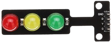
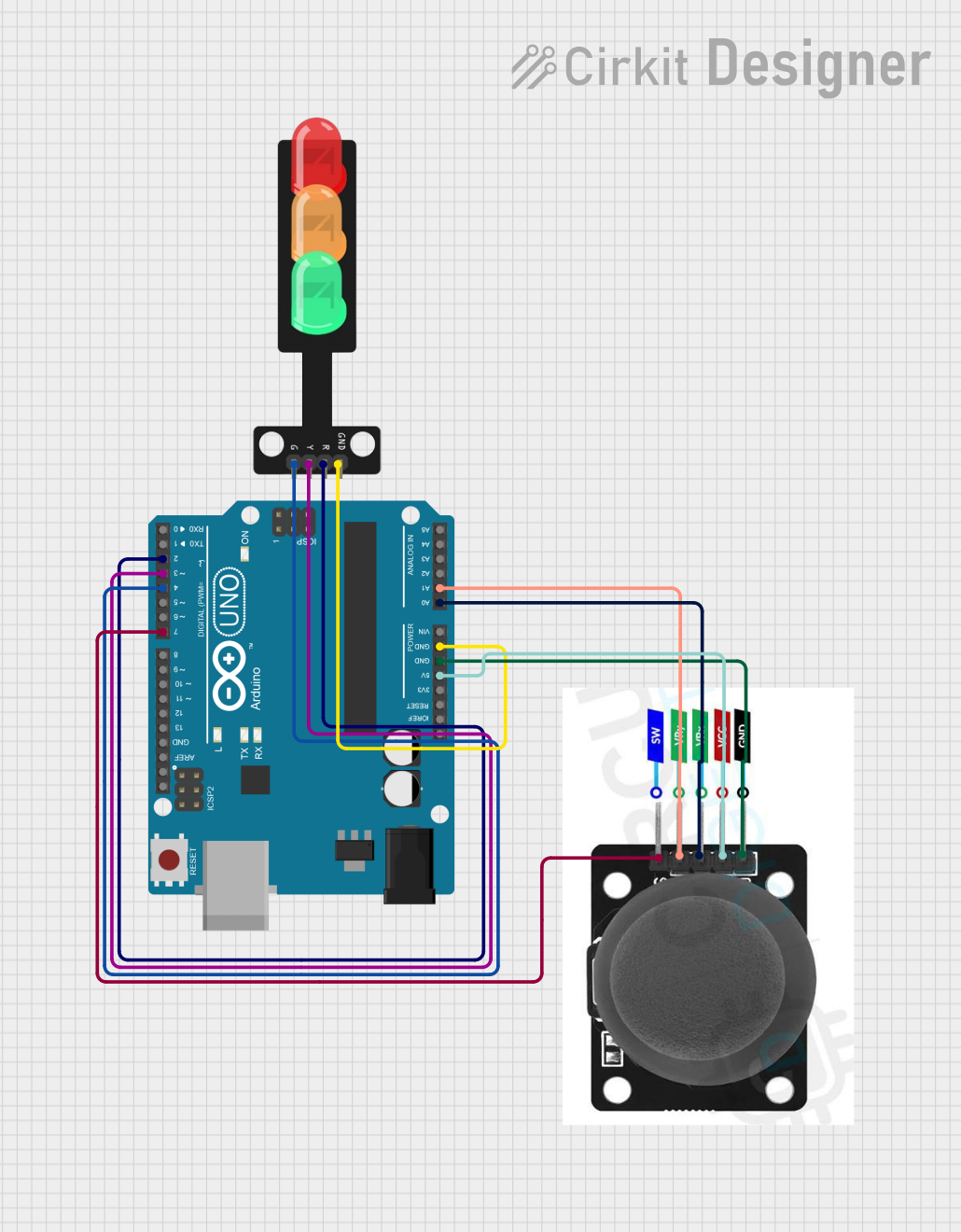
The Traffic Light Module (Manufacturer: CE, Part ID: DE) is a compact and easy-to-use electronic device designed to simulate the functionality of a standard traffic light. It features three LEDs (red, yellow, and green) that represent the stop, caution, and go signals, respectively. This module is widely used in educational projects, traffic system simulations, and embedded system applications. It is an excellent tool for learning about timing, sequencing, and control in electronics.
Explore Projects Built with Traaffic Light Module
Explore Projects Built with Traaffic Light Module
Common Applications and Use Cases
- Traffic system simulations for educational purposes
- Arduino and microcontroller-based projects
- Prototyping smart traffic management systems
- Demonstrating timing and sequencing concepts in electronics
- Robotics and automation projects requiring visual signaling
Technical Specifications
The following table outlines the key technical details of the Traffic Light Module:
| Parameter | Specification |
|---|---|
| Operating Voltage | 5V DC |
| Current Consumption | 20mA (typical) |
| LED Colors | Red, Yellow, Green |
| Dimensions | 30mm x 20mm x 10mm |
| Mounting Type | PCB Mountable |
| Interface | 3-pin header (VCC, GND, Signal) |
Pin Configuration and Descriptions
The module has a 3-pin header for easy interfacing. The pinout is as follows:
| Pin | Name | Description |
|---|---|---|
| 1 | VCC | Connect to a 5V DC power supply |
| 2 | GND | Connect to the ground of the power supply |
| 3 | Signal | Input signal to control the LEDs (active HIGH logic) |
Usage Instructions
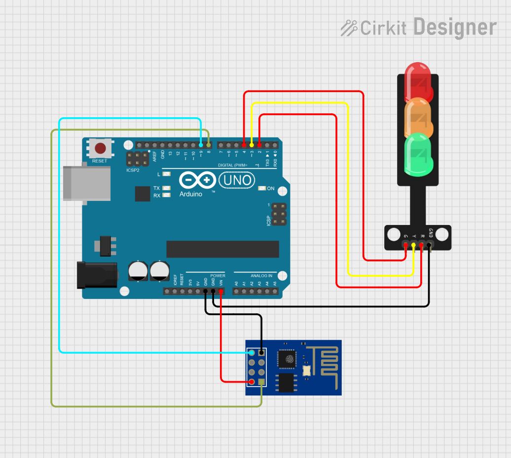
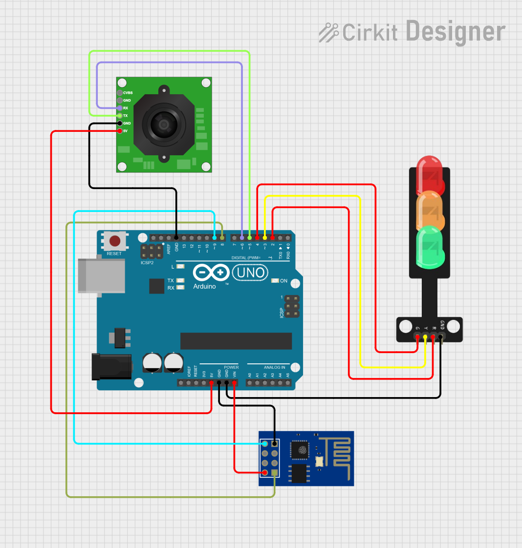
How to Use the Component in a Circuit
- Power the Module: Connect the
VCCpin to a 5V DC power source and theGNDpin to the ground. - Control the LEDs: Use the
Signalpin to control the LEDs. A HIGH signal will turn on the corresponding LED, while a LOW signal will turn it off. - Sequence the LEDs: To simulate a traffic light, sequence the LEDs in the following order:
- Red: ON for stop
- Yellow: ON for caution
- Green: ON for go
Important Considerations and Best Practices
- Ensure the module is powered with a stable 5V DC supply to avoid damage.
- Use current-limiting resistors if connecting directly to GPIO pins of a microcontroller.
- Avoid exposing the module to high temperatures or moisture to maintain its longevity.
- If using with an Arduino, ensure the
Signalpin is connected to a digital output pin.
Example Code for Arduino UNO
Below is an example Arduino sketch to control the Traffic Light Module:
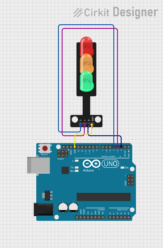
// Define pin connections for the Traffic Light Module
const int redPin = 8;    // Red LED connected to digital pin 8
const int yellowPin = 9; // Yellow LED connected to digital pin 9
const int greenPin = 10; // Green LED connected to digital pin 10

void setup() {
  // Set the LED pins as outputs
  pinMode(redPin, OUTPUT);
  pinMode(yellowPin, OUTPUT);
  pinMode(greenPin, OUTPUT);
}

void loop() {
  // Turn on the red LED (Stop)
  digitalWrite(redPin, HIGH);
  delay(5000); // Wait for 5 seconds
  digitalWrite(redPin, LOW);

  // Turn on the yellow LED (Caution)
  digitalWrite(yellowPin, HIGH);
  delay(2000); // Wait for 2 seconds
  digitalWrite(yellowPin, LOW);

  // Turn on the green LED (Go)
  digitalWrite(greenPin, HIGH);
  delay(5000); // Wait for 5 seconds
  digitalWrite(greenPin, LOW);
}
Troubleshooting and FAQs
Common Issues Users Might Face
LEDs Not Lighting Up:
- Ensure the module is connected to a 5V DC power supply.
- Check the wiring and ensure the
Signalpin is receiving the correct input.
Incorrect LED Sequence:
- Verify the control logic in your code.
- Ensure the correct pins are assigned to the red, yellow, and green LEDs.
Module Overheating:
- Check for overvoltage or excessive current draw.
- Use current-limiting resistors if necessary.
Solutions and Tips for Troubleshooting
- Use a multimeter to check the voltage at the
VCCandSignalpins. - Test each LED individually by applying a HIGH signal to the
Signalpin. - If using an Arduino, ensure the board is properly powered and the code is uploaded correctly.
By following this documentation, you can effectively integrate and use the CE Traffic Light Module (Part ID: DE) in your projects.