How to Use ESPC2-12: Examples, Pinouts, and Specs
Introduction
The ESPC2-12 is a compact, low-power microcontroller module featuring built-in Wi-Fi connectivity, making it an ideal choice for Internet of Things (IoT) applications. Based on the ESP8266 chip, this module is designed to provide seamless wireless communication and supports a variety of communication protocols, including HTTP, MQTT, and WebSocket. Its small form factor and energy-efficient design make it suitable for remote monitoring, smart home devices, and industrial automation.
Explore Projects Built with ESPC2-12
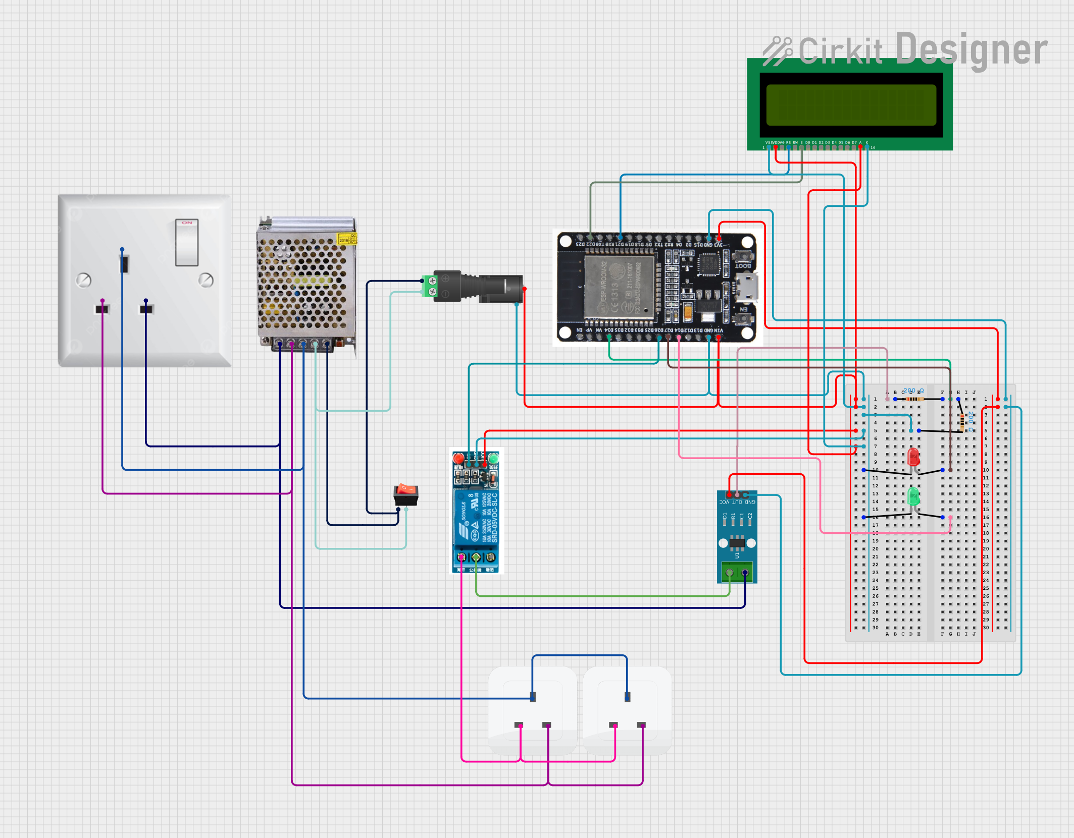
Explore Projects Built with ESPC2-12
Common Applications and Use Cases
- Smart home automation (e.g., controlling lights, thermostats, and appliances)
- Remote monitoring systems (e.g., temperature, humidity, or motion sensors)
- Industrial IoT (e.g., machine status monitoring and control)
- Wireless data logging and transmission
- DIY electronics and prototyping projects
Technical Specifications
Key Technical Details
| Parameter | Value |
|---|---|
| Microcontroller | ESP8266 |
| Operating Voltage | 3.0V - 3.6V |
| Wi-Fi Standard | 802.11 b/g/n |
| Flash Memory | 4 MB |
| GPIO Pins | 11 |
| Communication Protocols | UART, SPI, I2C, PWM, HTTP, MQTT |
| Power Consumption | 20 mA (idle), 200 mA (peak TX) |
| Operating Temperature | -40°C to 85°C |
| Dimensions | 24 mm x 16 mm x 3 mm |
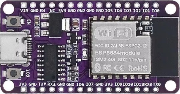
Pin Configuration and Descriptions
| Pin Number | Pin Name | Description |
|---|---|---|
| 1 | GND | Ground pin |
| 2 | VCC | Power supply input (3.0V - 3.6V) |
| 3 | TX | UART Transmit pin for serial communication |
| 4 | RX | UART Receive pin for serial communication |
| 5 | GPIO0 | General-purpose I/O pin, can be used for PWM |
| 6 | GPIO1 | General-purpose I/O pin, can be used for SPI |
| 7 | GPIO2 | General-purpose I/O pin, can be used for I2C |
| 8 | GPIO3 | General-purpose I/O pin, can be used for input |
| 9 | EN | Enable pin, active HIGH to power the module |
| 10 | RST | Reset pin, active LOW to reset the module |
| 11 | ADC | Analog-to-digital converter input (0V - 1V) |
Usage Instructions
How to Use the ESPC2-12 in a Circuit
- Power Supply: Connect the VCC pin to a regulated 3.3V power source and the GND pin to ground. Avoid exceeding the voltage range to prevent damage.
- Serial Communication: Use the TX and RX pins to communicate with a microcontroller or computer via UART. A USB-to-serial adapter can be used for programming.
- GPIO Pins: Configure the GPIO pins as input or output depending on your application. These pins can also be used for PWM, SPI, or I2C communication.
- Wi-Fi Setup: Use AT commands or custom firmware (e.g., NodeMCU or Arduino) to configure the Wi-Fi connection.
- Programming: Flash the ESPC2-12 with your desired firmware using tools like the Arduino IDE or ESP8266 Flasher.
Important Considerations and Best Practices
- Voltage Regulation: Ensure the power supply is stable and within the specified range (3.0V - 3.6V). Use a voltage regulator if necessary.
- Heat Management: Avoid prolonged operation at peak power consumption to prevent overheating.
- Pull-Up Resistors: Use pull-up resistors on the EN and RST pins for reliable operation.
- Firmware Updates: Keep the firmware updated to ensure compatibility and security.
Example: Connecting ESPC2-12 to an Arduino UNO
Below is an example of how to connect the ESPC2-12 to an Arduino UNO and send data to a Wi-Fi network.
Circuit Connections
- Connect the ESPC2-12's VCC to the Arduino's 3.3V pin.
- Connect the ESPC2-12's GND to the Arduino's GND.
- Connect the ESPC2-12's TX to the Arduino's RX (pin 0).
- Connect the ESPC2-12's RX to the Arduino's TX (pin 1) through a voltage divider to step down the 5V signal to 3.3V.
Arduino Code
#include <SoftwareSerial.h>

// Define RX and TX pins for SoftwareSerial
SoftwareSerial espSerial(2, 3); // RX, TX

void setup() {
  Serial.begin(9600); // Start serial communication with the PC
  espSerial.begin(9600); // Start serial communication with ESPC2-12

  Serial.println("Initializing ESPC2-12...");
  espSerial.println("AT"); // Send AT command to check communication
}

void loop() {
  // Check if data is available from ESPC2-12
  if (espSerial.available()) {
    String response = espSerial.readString();
    Serial.println("From ESPC2-12: " + response);
  }

  // Check if data is available from the PC
  if (Serial.available()) {
    String command = Serial.readString();
    espSerial.println(command); // Send command to ESPC2-12
  }
}
Troubleshooting and FAQs
Common Issues and Solutions
Module Not Responding to AT Commands
- Ensure the ESPC2-12 is powered correctly (3.3V).
- Check the TX and RX connections. Ensure they are not swapped.
- Verify the baud rate matches the module's default (usually 9600 or 115200).
Wi-Fi Connection Fails
- Double-check the SSID and password for the Wi-Fi network.
- Ensure the Wi-Fi network is within range and supports 2.4 GHz (not 5 GHz).
Overheating
- Reduce the duty cycle of high-power operations.
- Ensure proper ventilation around the module.
Flashing Firmware Fails
- Use a reliable USB-to-serial adapter with 3.3V logic levels.
- Hold the GPIO0 pin LOW during the flashing process.
FAQs
Q: Can the ESPC2-12 operate on 5V?
A: No, the ESPC2-12 requires a regulated 3.3V power supply. Using 5V can damage the module.
Q: How many devices can the ESPC2-12 connect to simultaneously?
A: The ESPC2-12 can act as a Wi-Fi access point and support up to 4 clients simultaneously.
Q: Can I use the ESPC2-12 with a battery?
A: Yes, you can use a 3.7V LiPo battery with a voltage regulator to provide a stable 3.3V supply.
Q: Is the ESPC2-12 compatible with the Arduino IDE?
A: Yes, the ESPC2-12 can be programmed using the Arduino IDE with the ESP8266 board package installed.