
How to Use USB2AX: Examples, Pinouts, and Specs
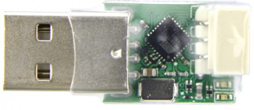
 Design with USB2AX in Cirkit Designer
Introduction
The USB2AX is a USB-to-AX (Analog) converter designed to bridge the gap between digital USB devices and analog systems. It enables seamless communication and data transfer between these two environments, making it an essential component for applications requiring integration of modern USB devices with legacy analog systems. The USB2AX is compact, efficient, and easy to use, making it suitable for a wide range of projects.
Explore Projects Built with USB2AX
 Open Project in Cirkit Designer
 Open Project in Cirkit Designer
 Open Project in Cirkit Designer
 Open Project in Cirkit Designer
Explore Projects Built with USB2AX
Open Project in Cirkit DesignerOpen Project in Cirkit DesignerOpen Project in Cirkit DesignerOpen Project in Cirkit DesignerCommon Applications and Use Cases
- Robotics: Connecting USB-based controllers to analog servo motors.
- Industrial automation: Bridging USB devices with analog control systems.
- Prototyping: Testing and debugging analog systems using USB tools.
- Data acquisition: Transferring data from analog sensors to USB-enabled devices.
- Educational projects: Demonstrating USB-to-analog communication principles.
Technical Specifications
The USB2AX is designed to provide reliable and efficient conversion between USB and analog signals. Below are its key technical specifications:
| Parameter | Value |
|---|---|
| Input Voltage | 5V (via USB) |
| Output Voltage Range | 0-5V (analog output) |
| Communication Protocol | USB 2.0 |
| Analog Resolution | 10-bit (1024 levels) |
| Current Consumption | 50mA (typical) |
| Operating Temperature | -20°C to 70°C |
| Dimensions | 40mm x 20mm x 10mm |
Pin Configuration and Descriptions
The USB2AX features a simple pinout for easy integration into circuits. Below is the pin configuration:
| Pin Name | Type | Description |
|---|---|---|
| VCC | Power Input | 5V power input from USB. |
| GND | Ground | Ground connection. |
| AX_OUT | Analog Output | Outputs the converted analog signal (0-5V range). |
| RX | Digital Input | Receives data from the USB device. |
| TX | Digital Output | Transmits data to the USB device. |
Usage Instructions
How to Use the USB2AX in a Circuit
- Power the USB2AX: Connect the USB2AX to a USB port or a 5V USB power source. Ensure the VCC and GND pins are properly connected.
- Connect the Analog System: Attach the AX_OUT pin to the input of your analog system (e.g., a servo motor or an analog sensor).
- Establish Communication: Use the RX and TX pins to communicate with the USB device. Ensure proper baud rate and protocol settings.
- Test the Setup: Verify the output voltage on the AX_OUT pin using a multimeter or oscilloscope to ensure proper operation.
Important Considerations and Best Practices
- Voltage Compatibility: Ensure the analog system operates within the 0-5V range to avoid damage.
- Signal Noise: Use proper grounding and shielding to minimize noise in the analog signal.
- Data Rate: Configure the USB device to match the data rate supported by the USB2AX for smooth communication.
- Heat Management: Avoid operating the USB2AX in environments exceeding its maximum temperature rating (70°C).
Example: Using USB2AX with Arduino UNO
The USB2AX can be easily interfaced with an Arduino UNO for controlling analog devices. Below is an example code snippet:
// Example: Sending data from Arduino UNO to USB2AX
// This code generates a PWM signal to control the analog output of USB2AX.

const int pwmPin = 9; // PWM pin connected to USB2AX RX pin

void setup() {
  pinMode(pwmPin, OUTPUT); // Set the PWM pin as output
}

void loop() {
  // Generate a PWM signal with varying duty cycle
  for (int dutyCycle = 0; dutyCycle <= 255; dutyCycle += 5) {
    analogWrite(pwmPin, dutyCycle); // Write PWM signal to USB2AX
    delay(50); // Wait for 50ms
  }
  for (int dutyCycle = 255; dutyCycle >= 0; dutyCycle -= 5) {
    analogWrite(pwmPin, dutyCycle); // Decrease PWM signal
    delay(50); // Wait for 50ms
  }
}
Troubleshooting and FAQs
Common Issues and Solutions
No Output on AX_OUT Pin
- Cause: Incorrect wiring or insufficient power supply.
- Solution: Verify all connections and ensure the USB2AX is receiving 5V power.
Signal Noise or Instability
- Cause: Poor grounding or interference from nearby components.
- Solution: Use a common ground for all components and shield the analog signal wires.
Communication Failure
- Cause: Mismatched baud rate or protocol settings.
- Solution: Check the USB device's communication settings and ensure they match the USB2AX requirements.
Overheating
- Cause: Operating in high-temperature environments or excessive current draw.
- Solution: Ensure proper ventilation and avoid exceeding the maximum current rating.
FAQs
Q: Can the USB2AX output negative voltages?
A: No, the USB2AX outputs voltages in the range of 0-5V only.
Q: Is the USB2AX compatible with USB 3.0 ports?
A: Yes, the USB2AX is backward compatible with USB 3.0 ports, but it operates at USB 2.0 speeds.
Q: Can I use the USB2AX with a 3.3V analog system?
A: Yes, but you will need a voltage divider or level shifter to step down the 5V output to 3.3V.
Q: How do I update the firmware on the USB2AX?
A: Firmware updates can be performed via the USB interface using the manufacturer's software tools. Refer to the official documentation for detailed instructions.