How to Use Octocoupler: Examples, Pinouts, and Specs
Introduction
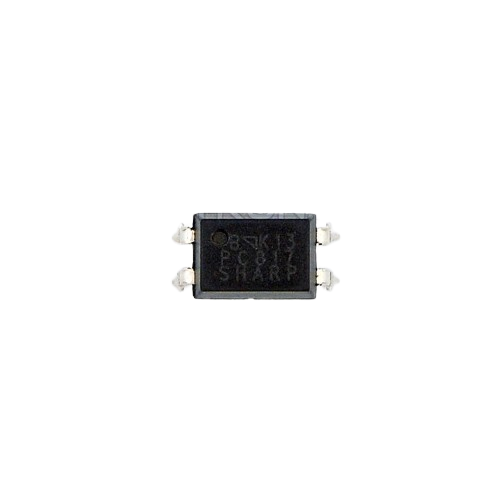
The SH615 Octocoupler, manufactured by Velsay, is an opto-isolator designed to transfer electrical signals between two isolated circuits using light. This component provides electrical isolation, ensuring that high voltages on one side of the circuit do not damage sensitive components on the other side. The SH615 is widely used in applications requiring signal isolation, noise reduction, and protection from voltage spikes.
Explore Projects Built with Octocoupler

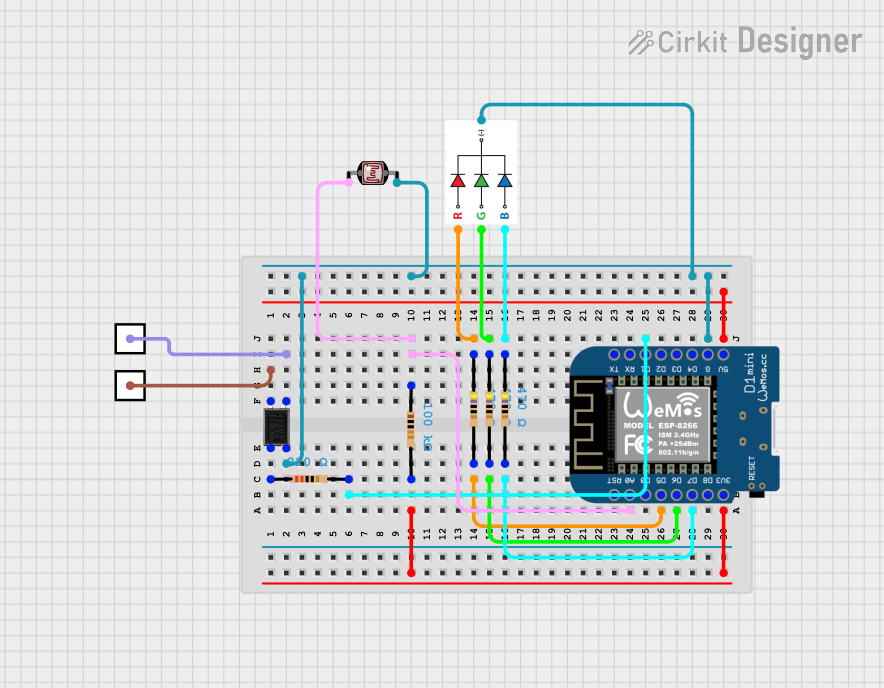

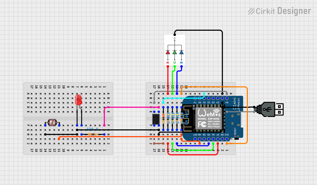
Explore Projects Built with Octocoupler
Common Applications
- Microcontroller interfacing with high-voltage circuits
- Signal isolation in industrial control systems
- Noise suppression in communication systems
- Protection of sensitive components in power electronics
- Motor control and switching circuits
Technical Specifications
The SH615 Octocoupler is a robust and versatile component with the following key specifications:
| Parameter | Value |
|---|---|
| Manufacturer | Velsay |
| Part Number | SH615 |
| Isolation Voltage | 5000 Vrms |
| Forward Voltage (LED) | 1.2 V (typical) |
| Forward Current (LED) | 10 mA (typical), 20 mA (maximum) |
| Collector-Emitter Voltage | 35 V (maximum) |
| Current Transfer Ratio (CTR) | 50% to 600% |
| Operating Temperature Range | -40°C to +100°C |
| Package Type | DIP-6 or SMD |
Pin Configuration and Descriptions
The SH615 is typically available in a 6-pin DIP (Dual Inline Package) configuration. The pinout is as follows:
| Pin Number | Name | Description |
|---|---|---|
| 1 | Anode (LED) | Positive terminal of the internal LED. Connect to the input signal. |
| 2 | Cathode (LED) | Negative terminal of the internal LED. Connect to ground or the signal return. |
| 3 | NC (No Connect) | Not connected internally. Leave unconnected or use as a mechanical support. |
| 4 | Emitter (Transistor) | Emitter terminal of the output phototransistor. Connect to ground. |
| 5 | Collector (Transistor) | Collector terminal of the output phototransistor. Connect to the load. |
| 6 | NC (No Connect) | Not connected internally. Leave unconnected or use as a mechanical support. |
Usage Instructions
How to Use the SH615 in a Circuit
Input Side (LED):
- Connect the anode (Pin 1) to the positive side of the input signal through a current-limiting resistor.
- Connect the cathode (Pin 2) to the ground or return path of the input signal.
- Calculate the resistor value using Ohm's Law:
[ R = \frac{V_{in} - V_f}{I_f} ]
Where (V_{in}) is the input voltage, (V_f) is the forward voltage of the LED (1.2 V), and (I_f) is the desired forward current (e.g., 10 mA).
Output Side (Phototransistor):
- Connect the collector (Pin 5) to the positive supply voltage through a pull-up resistor.
- Connect the emitter (Pin 4) to ground.
- The output signal can be read across the pull-up resistor. When the LED is on, the phototransistor conducts, pulling the output low.
Important Considerations
- Current Limiting: Always use a resistor in series with the LED to prevent overcurrent damage.
- Isolation: Ensure that the input and output circuits are electrically isolated to maintain the integrity of the isolation barrier.
- CTR Selection: Choose a pull-up resistor value that matches the desired current transfer ratio (CTR) for your application.
- Temperature Effects: Be aware of temperature variations, as they can affect the CTR and overall performance.
Example: Connecting SH615 to an Arduino UNO
The SH615 can be used to interface an Arduino UNO with a high-voltage circuit. Below is an example circuit and code:
Circuit Diagram
- Connect Pin 1 (Anode) to Arduino digital pin 9 through a 330 Ω resistor.
- Connect Pin 2 (Cathode) to Arduino GND.
- Connect Pin 5 (Collector) to a 5 V supply through a 10 kΩ pull-up resistor.
- Connect Pin 4 (Emitter) to GND.
- The output signal can be read at Pin 5.
Arduino Code
// Define the input and output pins
const int ledPin = 9;       // Arduino pin connected to SH615 Anode
const int outputPin = 2;    // Arduino pin to read the SH615 output

void setup() {
  pinMode(ledPin, OUTPUT);  // Set the LED pin as output
  pinMode(outputPin, INPUT);// Set the output pin as input
  Serial.begin(9600);       // Initialize serial communication
}

void loop() {
  // Turn the LED on and off
  digitalWrite(ledPin, HIGH); // Turn on the SH615 LED
  delay(1000);                // Wait for 1 second
  digitalWrite(ledPin, LOW);  // Turn off the SH615 LED
  delay(1000);                // Wait for 1 second

  // Read the output signal
  int outputState = digitalRead(outputPin);
  Serial.print("Output State: ");
  Serial.println(outputState); // Print the output state to the Serial Monitor
}
Troubleshooting and FAQs
Common Issues
No Output Signal:
- Cause: The LED current is too low.
- Solution: Check the current-limiting resistor value and ensure the LED forward current is within the recommended range (10-20 mA).
Output Signal is Always High:
- Cause: The pull-up resistor value is too high or the phototransistor is not conducting.
- Solution: Reduce the pull-up resistor value or check the LED circuit for proper operation.
Output Signal is Always Low:
- Cause: The LED is always on or the phototransistor is damaged.
- Solution: Verify the input signal and ensure the LED is not overdriven.
Excessive Heat:
- Cause: Overcurrent through the LED or phototransistor.
- Solution: Use appropriate resistors to limit current and ensure the component is within its operating range.
FAQs
Q: Can the SH615 handle AC signals?
A: Yes, the SH615 can handle AC signals on the input side, but you will need to use a rectifier circuit to ensure proper operation.
Q: What is the maximum isolation voltage?
A: The SH615 provides an isolation voltage of up to 5000 Vrms, making it suitable for high-voltage applications.
Q: Can I use the SH615 for PWM signals?
A: Yes, the SH615 can transmit PWM signals, but ensure the frequency is within the component's response time limits.
Q: How do I calculate the pull-up resistor value?
A: The pull-up resistor value depends on the desired current transfer ratio (CTR) and the supply voltage. A typical value is 10 kΩ for most applications.