Cirkit Designer Logo
Cirkit Designer
Your all-in-one circuit design IDE
Home / 
Component Documentation

How to Use NFC 4 Click ST25R3916: Examples, Pinouts, and Specs

Image of NFC 4 Click ST25R3916
Cirkit Designer LogoDesign with NFC 4 Click ST25R3916 in Cirkit Designer

Introduction

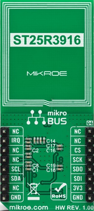
The NFC 4 Click ST25R3916 is a compact development board designed by Mikroe and powered by the ST25R3916 NFC/RFID reader IC. This versatile component supports multiple NFC modes, including reader, card emulation, and peer-to-peer communication, making it an excellent choice for a wide range of near-field communication (NFC) applications. Its high-performance design ensures reliable communication with NFC-enabled devices, making it ideal for prototyping and integrating NFC functionality into various projects.

Explore Projects Built with NFC 4 Click ST25R3916

Use Cirkit Designer to design, explore, and prototype these projects online. Some projects support real-time simulation. Click "Open Project" to start designing instantly!
NFC-Enabled Access Control System with Time Logging
Image of doorlock: A project utilizing NFC 4 Click ST25R3916 in a practical application
This circuit is designed for access control with time tracking capabilities. It features an NFC/RFID reader for authentication, an RTC module (DS3231) for real-time clock functionality, and an OLED display for user interaction. A 12V relay controls a magnetic lock, which is activated upon successful NFC/RFID authentication, and a button switch is likely used for manual operation or input. The T8_S3 microcontroller serves as the central processing unit, interfacing with the NFC/RFID reader, RTC, OLED, and relay to manage the access control logic.
Cirkit Designer LogoOpen Project in Cirkit Designer
NFC-Enabled Access Control System with Real-Time Clock and OLED Display
Image of doorlock: A project utilizing NFC 4 Click ST25R3916 in a practical application
This circuit is designed as an access control system with time-tracking capabilities. It uses an NFC/RFID reader for authentication, a real-time clock for time-stamping events, and an OLED display for user interface, all controlled by a T8_S3 microcontroller. A relay module actuates a magnetic lock, and a button switch provides additional user input, with a switching power supply delivering the necessary voltages.
Cirkit Designer LogoOpen Project in Cirkit Designer
Arduino UNO Based NFC Reader with Membrane Keypad Interface
Image of NFC_serial: A project utilizing NFC 4 Click ST25R3916 in a practical application
This circuit features an Arduino UNO connected to a 4x4 membrane matrix keypad, an NFC/RFID reader, and powered by a 9V battery. The Arduino is programmed to detect and display keypad inputs and read NFC tags, likely for an access control or identification system. The NFC/RFID reader communicates with the Arduino via I2C (using SDA and SCL lines), and the keypad is interfaced using digital IO pins.
Cirkit Designer LogoOpen Project in Cirkit Designer
STM32F103C8T6 Bluetooth-Controlled Arcade Joystick Interface
Image of RC카 조이스틱: A project utilizing NFC 4 Click ST25R3916 in a practical application
This circuit features an STM32F103C8T6 microcontroller interfaced with a Bluetooth HC-06 module for wireless communication and an Adafruit Arcade Joystick for user input. The microcontroller's pins B0 and B10 are connected to the TXD and RXD pins of the Bluetooth module, enabling serial communication, while pins B14 and B15 interface with the joystick's directional controls. The circuit is powered by a battery, with power distribution managed through the microcontroller's 3.3V pin and common ground connections.
Cirkit Designer LogoOpen Project in Cirkit Designer

Explore Projects Built with NFC 4 Click ST25R3916

Use Cirkit Designer to design, explore, and prototype these projects online. Some projects support real-time simulation. Click "Open Project" to start designing instantly!
Image of doorlock: A project utilizing NFC 4 Click ST25R3916 in a practical application
NFC-Enabled Access Control System with Time Logging
This circuit is designed for access control with time tracking capabilities. It features an NFC/RFID reader for authentication, an RTC module (DS3231) for real-time clock functionality, and an OLED display for user interaction. A 12V relay controls a magnetic lock, which is activated upon successful NFC/RFID authentication, and a button switch is likely used for manual operation or input. The T8_S3 microcontroller serves as the central processing unit, interfacing with the NFC/RFID reader, RTC, OLED, and relay to manage the access control logic.
Cirkit Designer LogoOpen Project in Cirkit Designer
Image of doorlock: A project utilizing NFC 4 Click ST25R3916 in a practical application
NFC-Enabled Access Control System with Real-Time Clock and OLED Display
This circuit is designed as an access control system with time-tracking capabilities. It uses an NFC/RFID reader for authentication, a real-time clock for time-stamping events, and an OLED display for user interface, all controlled by a T8_S3 microcontroller. A relay module actuates a magnetic lock, and a button switch provides additional user input, with a switching power supply delivering the necessary voltages.
Cirkit Designer LogoOpen Project in Cirkit Designer
Image of NFC_serial: A project utilizing NFC 4 Click ST25R3916 in a practical application
Arduino UNO Based NFC Reader with Membrane Keypad Interface
This circuit features an Arduino UNO connected to a 4x4 membrane matrix keypad, an NFC/RFID reader, and powered by a 9V battery. The Arduino is programmed to detect and display keypad inputs and read NFC tags, likely for an access control or identification system. The NFC/RFID reader communicates with the Arduino via I2C (using SDA and SCL lines), and the keypad is interfaced using digital IO pins.
Cirkit Designer LogoOpen Project in Cirkit Designer
Image of RC카 조이스틱: A project utilizing NFC 4 Click ST25R3916 in a practical application
STM32F103C8T6 Bluetooth-Controlled Arcade Joystick Interface
This circuit features an STM32F103C8T6 microcontroller interfaced with a Bluetooth HC-06 module for wireless communication and an Adafruit Arcade Joystick for user input. The microcontroller's pins B0 and B10 are connected to the TXD and RXD pins of the Bluetooth module, enabling serial communication, while pins B14 and B15 interface with the joystick's directional controls. The circuit is powered by a battery, with power distribution managed through the microcontroller's 3.3V pin and common ground connections.
Cirkit Designer LogoOpen Project in Cirkit Designer

Common Applications

  • Contactless payment systems
  • Access control and authentication
  • NFC-enabled IoT devices
  • Data exchange between NFC-enabled devices
  • Smart posters and tags
  • Inventory and asset tracking

Technical Specifications

Key Technical Details

Parameter Value
Manufacturer Mikroe
Part Number ST25R3916
Operating Voltage 3.3V
Communication Interface SPI
NFC Modes Supported Reader, Card Emulation, Peer-to-Peer
Operating Frequency 13.56 MHz
Maximum Output Power 1.4 W
Antenna Driver Current Up to 350 mA
ISO Standards Supported ISO 14443A/B, ISO 15693, ISO 18092
Operating Temperature Range -40°C to +85°C
Dimensions 42.9 mm x 25.4 mm

Pin Configuration and Descriptions

The NFC 4 Click board uses a standard mikroBUS™ socket for easy integration. Below is the pinout description:

Pin Name Pin Number Type Description
AN 1 Input General-purpose analog pin
RST 2 Input Reset pin for the ST25R3916 IC
CS 3 Input SPI chip select
SCK 4 Input SPI clock
MISO 5 Output SPI master-in/slave-out
MOSI 6 Input SPI master-out/slave-in
PWM 7 Output General-purpose PWM pin
INT 8 Output Interrupt signal from the IC
VCC 9 Power Power supply (3.3V)
GND 10 Ground Ground connection

Usage Instructions

How to Use the Component in a Circuit

  1. Power Supply: Connect the NFC 4 Click to a 3.3V power source via the mikroBUS™ socket.
  2. SPI Communication: Ensure the SPI pins (CS, SCK, MISO, MOSI) are properly connected to your microcontroller or development board.
  3. Antenna Connection: The onboard antenna is pre-configured for NFC communication. No additional setup is required.
  4. Reset and Interrupt: Use the RST pin to reset the IC and monitor the INT pin for interrupt signals.
  5. Software Configuration: Use the provided Mikroe libraries or write custom SPI commands to configure the ST25R3916 for your desired NFC mode.

Important Considerations and Best Practices

  • Power Requirements: Ensure a stable 3.3V power supply to avoid communication errors.
  • Antenna Placement: Avoid placing the board near metal objects, as they can interfere with NFC communication.
  • SPI Configuration: Set the SPI clock speed and mode according to the ST25R3916 datasheet for optimal performance.
  • Interrupt Handling: Use the INT pin to detect events such as tag detection or communication errors.
  • Firmware Updates: Check for updates to Mikroe's libraries to ensure compatibility with the latest features.

Example Code for Arduino UNO

Below is an example of how to interface the NFC 4 Click with an Arduino UNO using SPI:

#include <SPI.h>

// Pin definitions for the NFC 4 Click
#define CS_PIN 10    // Chip Select pin
#define RST_PIN 9    // Reset pin
#define INT_PIN 2    // Interrupt pin

void setup() {
  // Initialize serial communication for debugging
  Serial.begin(9600);
  
  // Initialize SPI communication
  SPI.begin();
  pinMode(CS_PIN, OUTPUT);
  pinMode(RST_PIN, OUTPUT);
  pinMode(INT_PIN, INPUT);

  // Reset the NFC module
  digitalWrite(RST_PIN, LOW);
  delay(100);
  digitalWrite(RST_PIN, HIGH);
  delay(100);

  Serial.println("NFC 4 Click Initialized");
}

void loop() {
  // Example: Send a dummy SPI command to the NFC module
  digitalWrite(CS_PIN, LOW); // Select the NFC module
  SPI.transfer(0x00);        // Send a dummy command
  digitalWrite(CS_PIN, HIGH); // Deselect the NFC module

  // Check for interrupt signal
  if (digitalRead(INT_PIN) == HIGH) {
    Serial.println("Interrupt detected!");
    // Handle the interrupt (e.g., read tag data)
  }

  delay(500); // Wait for a while
}

Troubleshooting and FAQs

Common Issues and Solutions

  1. No Response from the NFC Module

    • Cause: Incorrect SPI configuration or wiring.
    • Solution: Double-check the SPI connections and ensure the SPI clock speed matches the ST25R3916 requirements.
  2. NFC Tag Not Detected

    • Cause: Improper antenna placement or interference.
    • Solution: Ensure the tag is within the NFC range and avoid placing the board near metal objects.
  3. Interrupt Pin Not Triggering

    • Cause: Incorrect interrupt handling or configuration.
    • Solution: Verify the INT pin connection and ensure the firmware is configured to enable interrupts.
  4. Power Supply Issues

    • Cause: Insufficient or unstable power supply.
    • Solution: Use a regulated 3.3V power source and check for voltage drops.

FAQs

  • Q: Can the NFC 4 Click work with 5V systems?
    A: No, the board operates at 3.3V. Use a level shifter if interfacing with a 5V system.

  • Q: What is the maximum NFC range?
    A: The range depends on the antenna and tag size but typically extends up to 10 cm.

  • Q: Does Mikroe provide software libraries for this board?
    A: Yes, Mikroe provides libraries and example code for various platforms, including Arduino and MikroC.

  • Q: Can I use this board for peer-to-peer communication?
    A: Yes, the ST25R3916 supports peer-to-peer NFC communication.


This documentation provides a comprehensive guide to using the NFC 4 Click ST25R3916. For further assistance, refer to the official Mikroe documentation or contact their support team.