How to Use Expansion board: Examples, Pinouts, and Specs

Introduction
The Tscinbuny Expansion Board is a versatile circuit board designed to extend the functionality of a primary circuit board, such as a microcontroller or development board. It provides additional connections, interfaces, and features, enabling users to integrate extra components or modules with ease. This expansion board is ideal for prototyping, educational projects, and applications requiring modularity and scalability.
Explore Projects Built with Expansion board


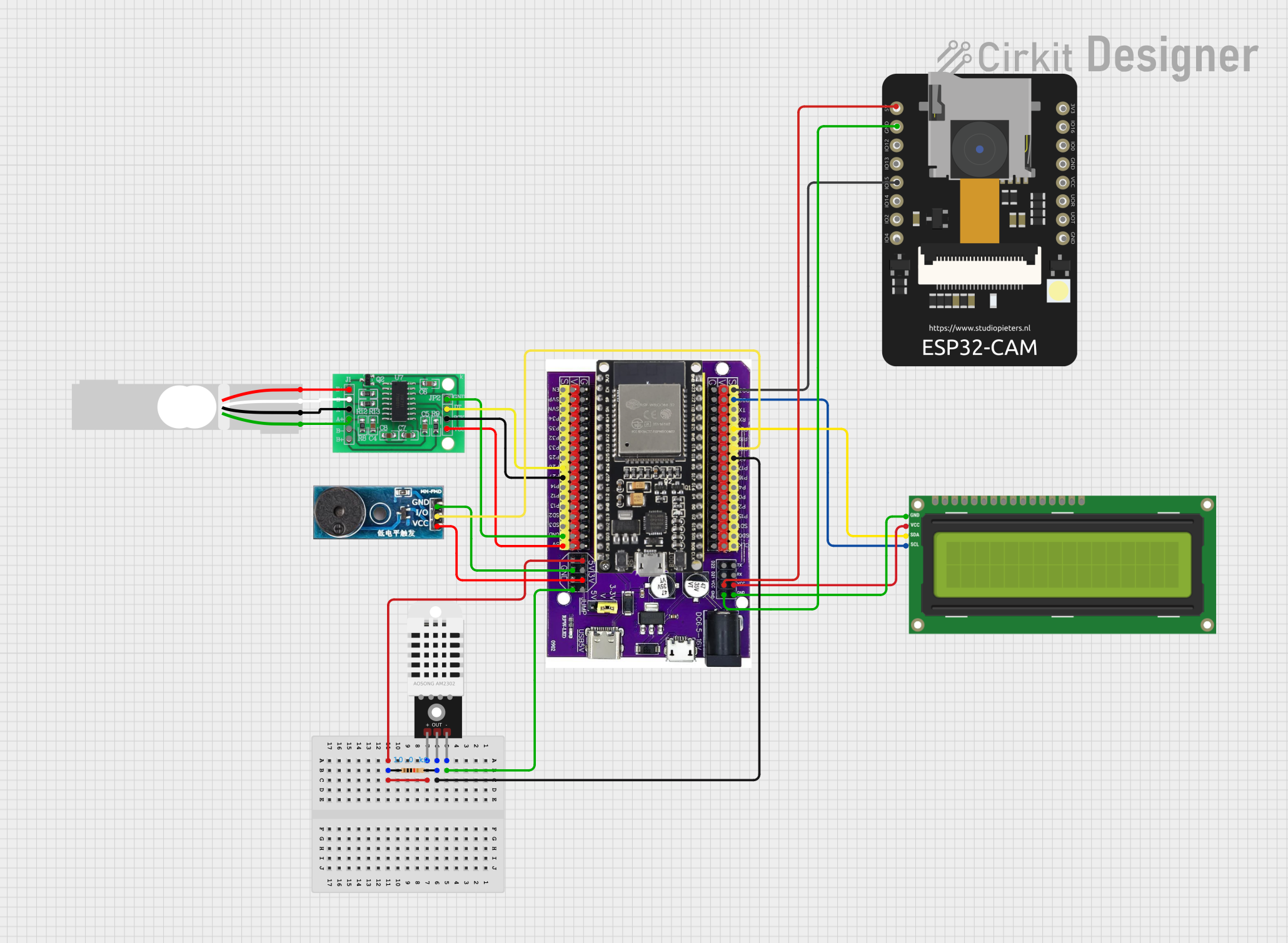
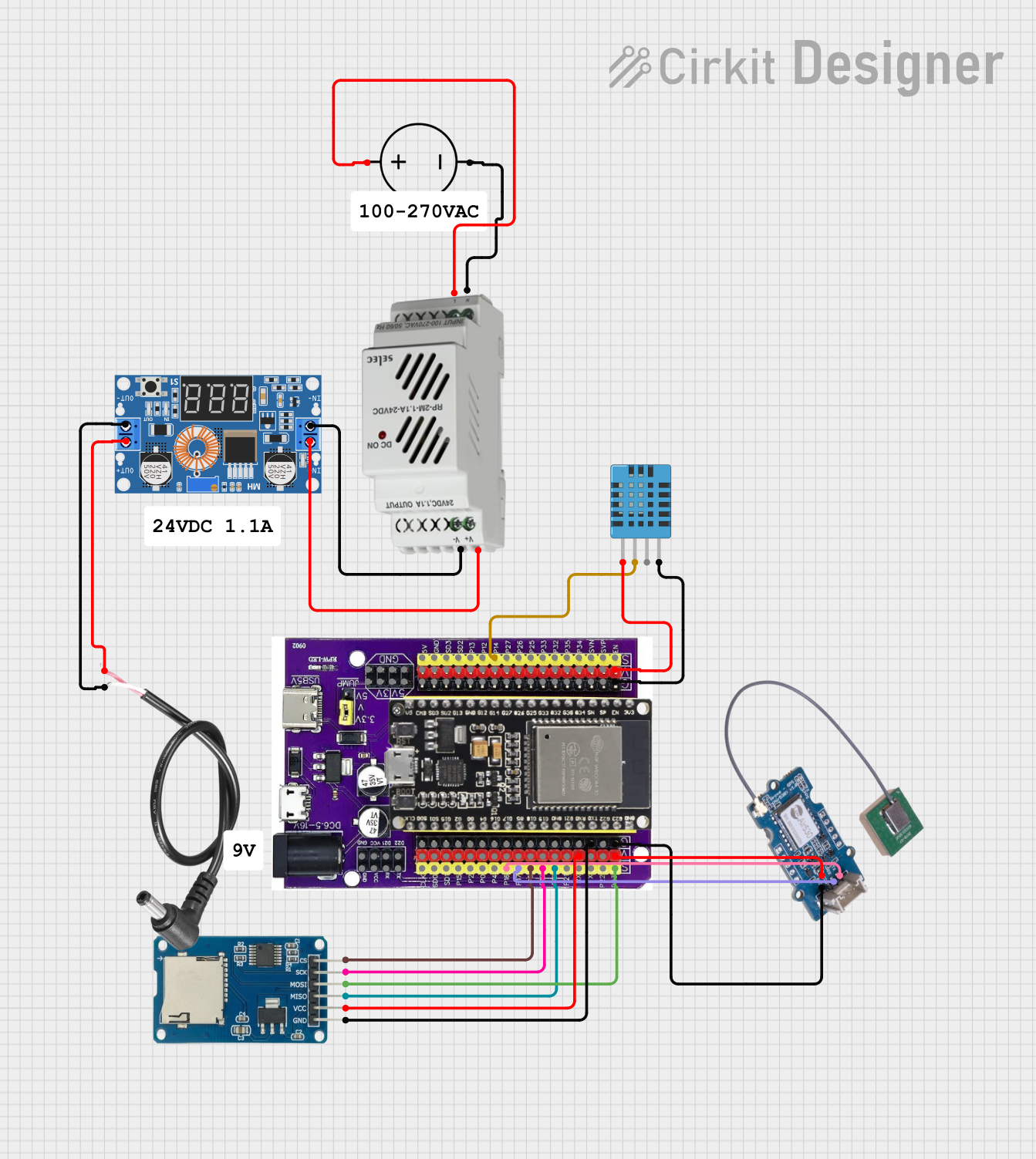
Explore Projects Built with Expansion board
Common Applications and Use Cases
- Prototyping and testing new circuits
- Adding extra GPIO pins, communication interfaces, or power connections
- Connecting sensors, actuators, or other peripherals to microcontrollers
- Educational and DIY electronics projects
- Industrial automation and IoT applications
Technical Specifications
The Tscinbuny Expansion Board is designed to be compatible with a wide range of microcontrollers and development boards, including Arduino, Raspberry Pi, and others. Below are the key technical details:
General Specifications
| Parameter | Value |
|---|---|
| Manufacturer | Tscinbuny |
| Part ID | Tscinbuny Expansion Board |
| Operating Voltage | 3.3V / 5V |
| Maximum Current | 2A |
| Dimensions | 70mm x 55mm x 15mm |
| Mounting Type | Through-hole or screw mount |
| Communication Interfaces | I2C, SPI, UART, GPIO |
| Operating Temperature | -20°C to 85°C |
Pin Configuration and Descriptions
The expansion board features a variety of pins and connectors to support multiple functionalities. Below is the pinout description:
GPIO and Power Pins
| Pin Label | Description | Voltage Level |
|---|---|---|
| VCC | Power input (3.3V or 5V) | 3.3V / 5V |
| GND | Ground connection | 0V |
| GPIO1 | General-purpose input/output pin 1 | Configurable |
| GPIO2 | General-purpose input/output pin 2 | Configurable |
| GPIO3 | General-purpose input/output pin 3 | Configurable |
| GPIO4 | General-purpose input/output pin 4 | Configurable |
Communication Interface Pins
| Pin Label | Description | Voltage Level |
|---|---|---|
| SDA | I2C data line | 3.3V / 5V |
| SCL | I2C clock line | 3.3V / 5V |
| MISO | SPI master-in/slave-out | 3.3V / 5V |
| MOSI | SPI master-out/slave-in | 3.3V / 5V |
| SCK | SPI clock | 3.3V / 5V |
| TX | UART transmit | 3.3V / 5V |
| RX | UART receive | 3.3V / 5V |
Usage Instructions
How to Use the Tscinbuny Expansion Board in a Circuit
- Power the Board: Connect the VCC pin to a 3.3V or 5V power source and the GND pin to ground.
- Connect to a Microcontroller: Use jumper wires or headers to connect the expansion board's communication pins (e.g., I2C, SPI, or UART) to the corresponding pins on your microcontroller.
- Attach Peripherals: Connect sensors, actuators, or other modules to the GPIO pins or communication interfaces.
- Configure the Pins: Program your microcontroller to configure the GPIO pins as inputs or outputs, and initialize the communication protocols as needed.
Important Considerations and Best Practices
- Voltage Compatibility: Ensure that the voltage levels of the connected devices match the operating voltage of the expansion board (3.3V or 5V).
- Avoid Overloading: Do not exceed the maximum current rating of 2A to prevent damage to the board.
- Secure Connections: Use proper connectors or solder the pins to ensure stable and reliable connections.
- Static Precautions: Handle the board with care to avoid damage from electrostatic discharge (ESD).
Example: Using the Expansion Board with an Arduino UNO
Below is an example of how to use the Tscinbuny Expansion Board with an Arduino UNO to read data from an I2C sensor:
Circuit Connections
- Connect the VCC pin of the expansion board to the 5V pin on the Arduino UNO.
- Connect the GND pin of the expansion board to the GND pin on the Arduino UNO.
- Connect the SDA and SCL pins of the expansion board to the A4 and A5 pins on the Arduino UNO, respectively.
Arduino Code
#include <Wire.h> // Include the Wire library for I2C communication

void setup() {
  Wire.begin(); // Initialize I2C communication
  Serial.begin(9600); // Start serial communication for debugging
  Serial.println("Tscinbuny Expansion Board Example");
}

void loop() {
  Wire.beginTransmission(0x68); // Start communication with I2C device at address 0x68
  Wire.write(0x00); // Send a command or register address
  Wire.endTransmission(); // End the transmission

  Wire.requestFrom(0x68, 1); // Request 1 byte of data from the I2C device
  if (Wire.available()) {
    int data = Wire.read(); // Read the received data
    Serial.print("Received Data: ");
    Serial.println(data); // Print the data to the Serial Monitor
  }

  delay(1000); // Wait for 1 second before repeating
}
Troubleshooting and FAQs
Common Issues and Solutions
No Power to the Board
- Cause: Incorrect power connection or insufficient power supply.
- Solution: Verify the VCC and GND connections and ensure the power source provides the required voltage and current.
Communication Failure
- Cause: Incorrect wiring or mismatched communication settings.
- Solution: Double-check the connections and ensure the communication protocol (I2C, SPI, or UART) is correctly configured in the microcontroller code.
Peripheral Not Responding
- Cause: Incorrect GPIO configuration or faulty peripheral.
- Solution: Verify the GPIO pin settings in the code and test the peripheral separately to ensure it is functioning.
Overheating
- Cause: Exceeding the maximum current rating.
- Solution: Reduce the load on the board and ensure the total current draw does not exceed 2A.
FAQs
Q1: Can the Tscinbuny Expansion Board be used with a Raspberry Pi?
A1: Yes, the board is compatible with Raspberry Pi. Ensure you use the correct GPIO pins and voltage levels (3.3V).
Q2: How many peripherals can I connect to the board?
A2: The number of peripherals depends on the available GPIO pins and communication interfaces. You can use multiplexers or expanders for additional connections.
Q3: Is the board compatible with 12V devices?
A3: No, the board operates at 3.3V or 5V. Use a voltage regulator or level shifter for 12V devices.
Q4: Can I stack multiple expansion boards?
A4: Yes, as long as the total current draw does not exceed 2A and there are no pin conflicts.