How to Use integrated circuit amplifier: Examples, Pinouts, and Specs
Introduction
An integrated circuit amplifier is a miniaturized electronic circuit that combines multiple components, such as transistors, resistors, and capacitors, into a single chip to amplify electrical signals. These amplifiers are widely used in various applications due to their efficiency, compact size, and reliability.
Explore Projects Built with integrated circuit amplifier
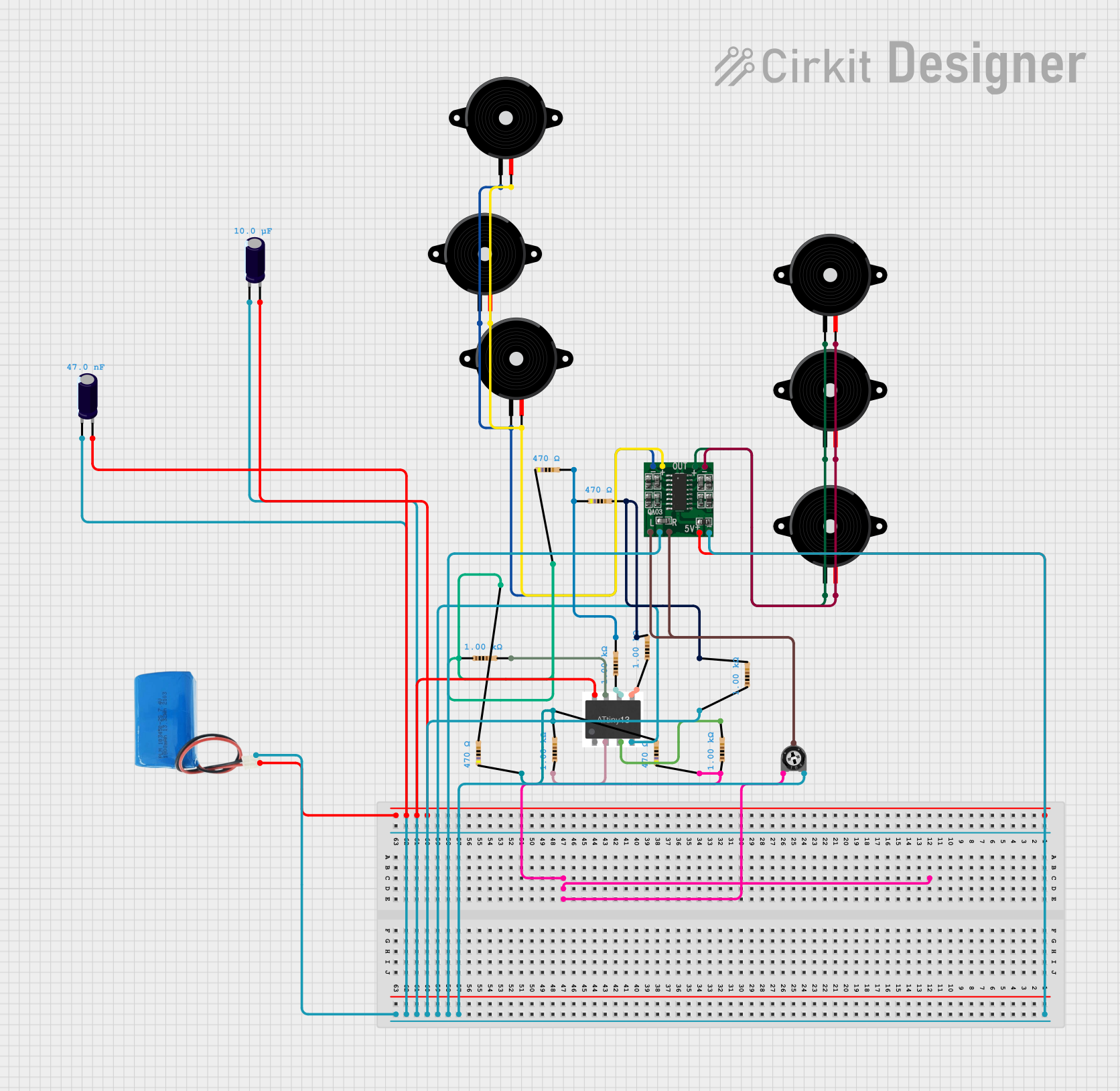
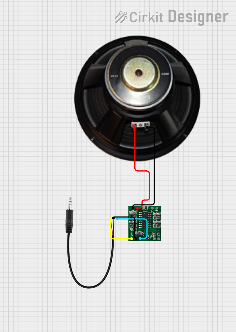
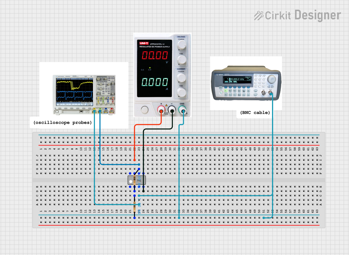

Explore Projects Built with integrated circuit amplifier
Common Applications and Use Cases:
- Audio Amplification: Used in audio systems to amplify sound signals for speakers or headphones.
- Radio Frequency (RF) Amplification: Enhances weak RF signals in communication systems.
- Signal Processing: Amplifies analog signals in sensors, instrumentation, and control systems.
- Operational Amplifiers (Op-Amps): Used in mathematical operations, filtering, and voltage regulation.
Technical Specifications
The technical specifications of an integrated circuit amplifier vary depending on the specific model and type. Below are general specifications for a typical operational amplifier (e.g., LM741):
Key Technical Details:
- Supply Voltage: ±5V to ±15V (dual supply) or 5V to 30V (single supply)
- Input Impedance: Typically 1 MΩ or higher
- Output Impedance: Low, typically less than 100 Ω
- Gain Bandwidth Product: 1 MHz (for LM741)
- Slew Rate: 0.5 V/μs
- Output Voltage Swing: Close to supply voltage (depending on the model)
- Power Consumption: Typically 0.5 mW to 10 mW
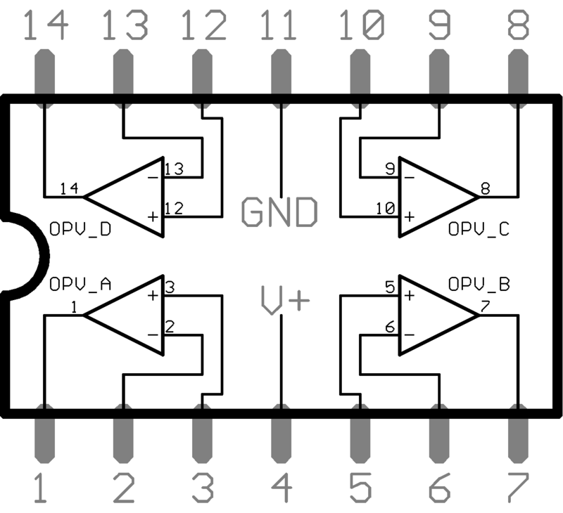
Pin Configuration and Descriptions:
Below is the pin configuration for a standard 8-pin dual in-line package (DIP) operational amplifier, such as the LM741:
| Pin Number | Pin Name | Description |
|---|---|---|
| 1 | Offset Null | Used to adjust the offset voltage of the amplifier. |
| 2 | Inverting Input (-) | Input where the signal is inverted (negative feedback). |
| 3 | Non-Inverting Input (+) | Input where the signal is applied without inversion. |
| 4 | V- (Negative Supply) | Negative power supply voltage. |
| 5 | Offset Null | Used in conjunction with Pin 1 for offset adjustment. |
| 6 | Output | Amplified output signal. |
| 7 | V+ (Positive Supply) | Positive power supply voltage. |
| 8 | Not Connected (NC) | No internal connection (may vary by model). |
Usage Instructions
How to Use the Component in a Circuit:
- Power Supply: Connect the positive supply voltage (V+) to Pin 7 and the negative supply voltage (V-) to Pin 4. For single-supply operation, connect V- to ground.
- Input Signal: Apply the input signal to either the inverting input (Pin 2) or the non-inverting input (Pin 3), depending on the desired configuration:
- Inverting Configuration: Connect the input signal to Pin 2 and ground Pin 3.
- Non-Inverting Configuration: Connect the input signal to Pin 3 and ground Pin 2.
- Feedback Resistor: Use a resistor between the output (Pin 6) and the inverting input (Pin 2) to set the gain of the amplifier.
- Output Signal: The amplified signal will be available at Pin 6.
Important Considerations and Best Practices:
- Bypass Capacitors: Place decoupling capacitors (e.g., 0.1 μF) close to the power supply pins to reduce noise.
- Input Impedance: Ensure the input impedance of the amplifier matches the source impedance for optimal performance.
- Thermal Management: Avoid exceeding the maximum power dissipation to prevent overheating.
- Stability: Use compensation capacitors if required to prevent oscillations in high-gain configurations.
Example: Connecting to an Arduino UNO
Below is an example of using an integrated circuit amplifier (e.g., LM358) to amplify an analog signal for an Arduino UNO:
/*
  Example: Amplifying an analog signal using LM358 and reading it with Arduino UNO.
  - The LM358 amplifies the signal from a sensor before feeding it to the Arduino.
  - Ensure proper power supply connections to the LM358 (V+ and V-).
*/

const int analogPin = A0; // Analog pin to read the amplified signal
int sensorValue = 0;      // Variable to store the analog reading

void setup() {
  Serial.begin(9600); // Initialize serial communication
}

void loop() {
  sensorValue = analogRead(analogPin); // Read the amplified signal
  Serial.print("Amplified Signal: ");
  Serial.println(sensorValue); // Print the value to the Serial Monitor
  delay(500); // Wait for 500 ms
}
Troubleshooting and FAQs
Common Issues and Solutions:
No Output Signal:
- Cause: Incorrect power supply connections.
- Solution: Verify that V+ and V- are connected to the correct voltage levels.
Distorted Output:
- Cause: Exceeding the input voltage range or insufficient power supply voltage.
- Solution: Ensure the input signal is within the amplifier's input voltage range and the power supply meets the required specifications.
Oscillations or Noise:
- Cause: Lack of proper decoupling or incorrect feedback configuration.
- Solution: Add bypass capacitors near the power supply pins and verify the feedback resistor values.
Overheating:
- Cause: Excessive power dissipation.
- Solution: Check the load impedance and ensure it is within the amplifier's specifications.
FAQs:
Q: Can I use an integrated circuit amplifier with a single power supply?
- A: Yes, many amplifiers support single-supply operation. Connect V- to ground and ensure the input signal is biased within the amplifier's input range.
Q: How do I calculate the gain of the amplifier?
- A: For an inverting amplifier, gain = -Rf/Rin, where Rf is the feedback resistor and Rin is the input resistor. For a non-inverting amplifier, gain = 1 + (Rf/Rin).
Q: What is the difference between an operational amplifier and a power amplifier?
- A: Operational amplifiers are designed for signal processing and have high input impedance and low output current. Power amplifiers are designed to drive high-current loads, such as speakers.
This documentation provides a comprehensive guide to understanding and using integrated circuit amplifiers effectively.