How to Use EC200U GSM: Examples, Pinouts, and Specs
Introduction
The EC200U GSM is a compact and versatile cellular module designed for Internet of Things (IoT) applications. It provides reliable 2G/3G connectivity, making it an excellent choice for devices requiring remote communication. With support for various communication protocols, the EC200U GSM is ideal for applications such as smart meters, asset tracking, industrial automation, and remote monitoring systems.
Explore Projects Built with EC200U GSM


Explore Projects Built with EC200U GSM
Common Applications and Use Cases
- Smart home devices and automation
- Remote monitoring and control systems
- Industrial IoT (IIoT) applications
- Asset tracking and fleet management
- Smart agriculture and environmental monitoring
- Point-of-sale (POS) terminals
Technical Specifications
Key Technical Details
| Parameter | Specification |
|---|---|
| Cellular Technology | GSM/GPRS/EDGE, UMTS/HSPA |
| Frequency Bands | GSM: 850/900/1800/1900 MHz |
| UMTS: 850/900/1900/2100 MHz | |
| Data Rates | HSPA: Uplink 5.76 Mbps, Downlink 7.2 Mbps |
| EDGE: Uplink 236.8 kbps, Downlink 236.8 kbps | |
| GPRS: Uplink 85.6 kbps, Downlink 85.6 kbps | |
| Operating Voltage | 3.3V to 4.3V |
| Power Consumption | Idle: < 1.5 mA, Active: < 500 mA |
| Operating Temperature | -40°C to +85°C |
| Dimensions | 29.0 mm × 32.0 mm × 2.4 mm |
| Communication Interfaces | UART, USB, I2C, GPIO |
| SIM Card Support | 1.8V/3.0V |
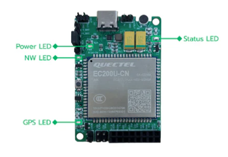
Pin Configuration and Descriptions
| Pin Number | Pin Name | Description |
|---|---|---|
| 1 | VCC | Power supply input (3.3V to 4.3V) |
| 2 | GND | Ground |
| 3 | TXD | UART Transmit Data |
| 4 | RXD | UART Receive Data |
| 5 | RTS | UART Request to Send |
| 6 | CTS | UART Clear to Send |
| 7 | USB_DP | USB Data Positive |
| 8 | USB_DM | USB Data Negative |
| 9 | SIM_VDD | SIM card power supply |
| 10 | SIM_DATA | SIM card data line |
| 11 | SIM_CLK | SIM card clock |
| 12 | SIM_RST | SIM card reset |
| 13 | GPIO1 | General-purpose input/output |
| 14 | GPIO2 | General-purpose input/output |
Usage Instructions
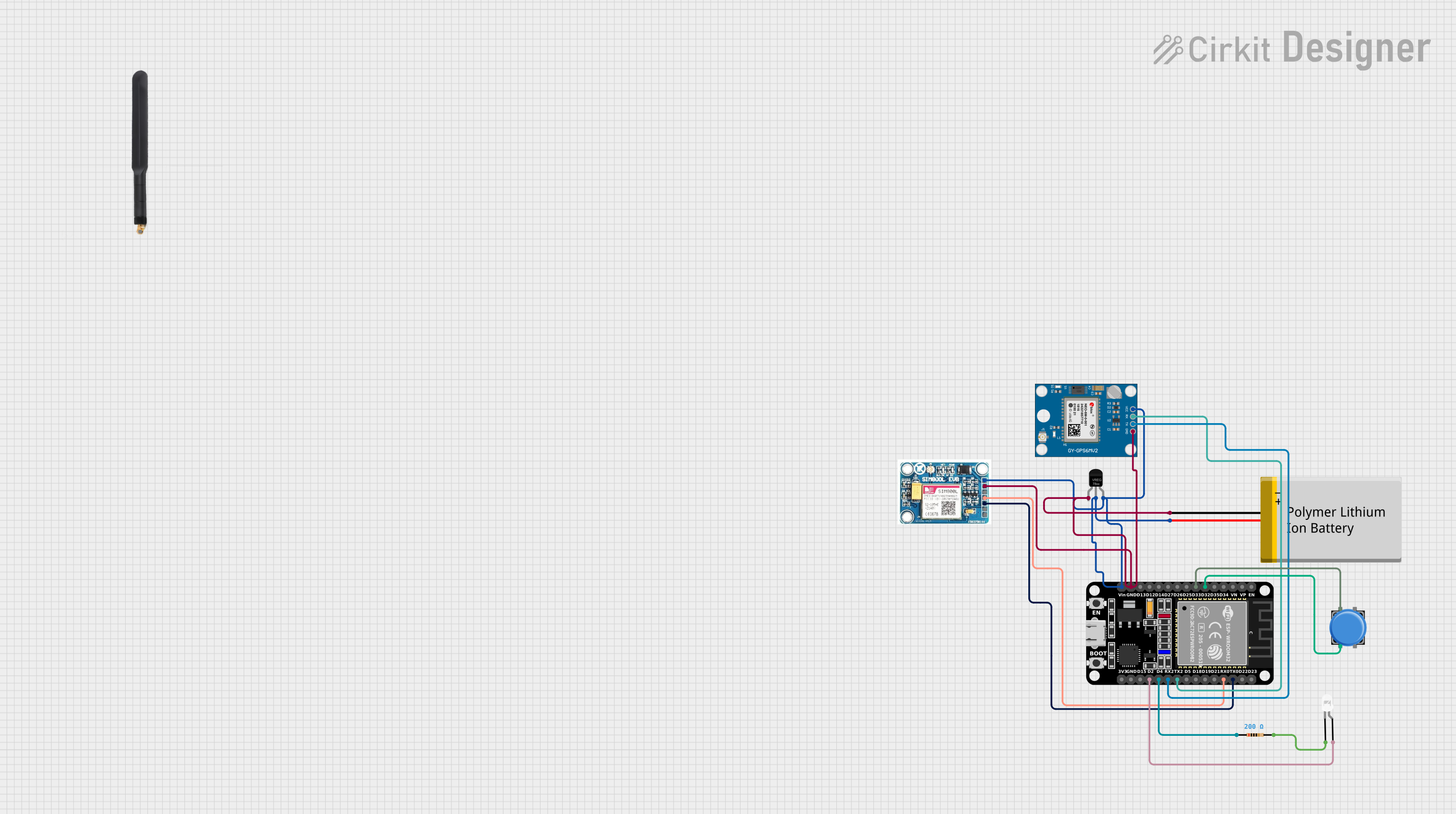
How to Use the EC200U GSM in a Circuit
- Power Supply: Connect the VCC pin to a stable power source (3.3V to 4.3V) and the GND pin to ground.
- UART Communication: Use the TXD and RXD pins to establish serial communication with a microcontroller or computer. Optionally, connect RTS and CTS for hardware flow control.
- SIM Card Connection: Connect the SIM_VDD, SIM_DATA, SIM_CLK, and SIM_RST pins to a compatible SIM card holder.
- Antenna: Attach an external antenna to the module's antenna connector for optimal signal reception.
- USB Interface: Use the USB_DP and USB_DM pins for USB communication if required.
Important Considerations and Best Practices
- Ensure the power supply is stable and within the specified voltage range to avoid damage to the module.
- Use decoupling capacitors near the VCC pin to filter out noise.
- Place the antenna away from high-frequency components to minimize interference.
- Use proper ESD protection when handling the module and connecting the SIM card.
- For UART communication, ensure the baud rate matches the settings of the connected device.
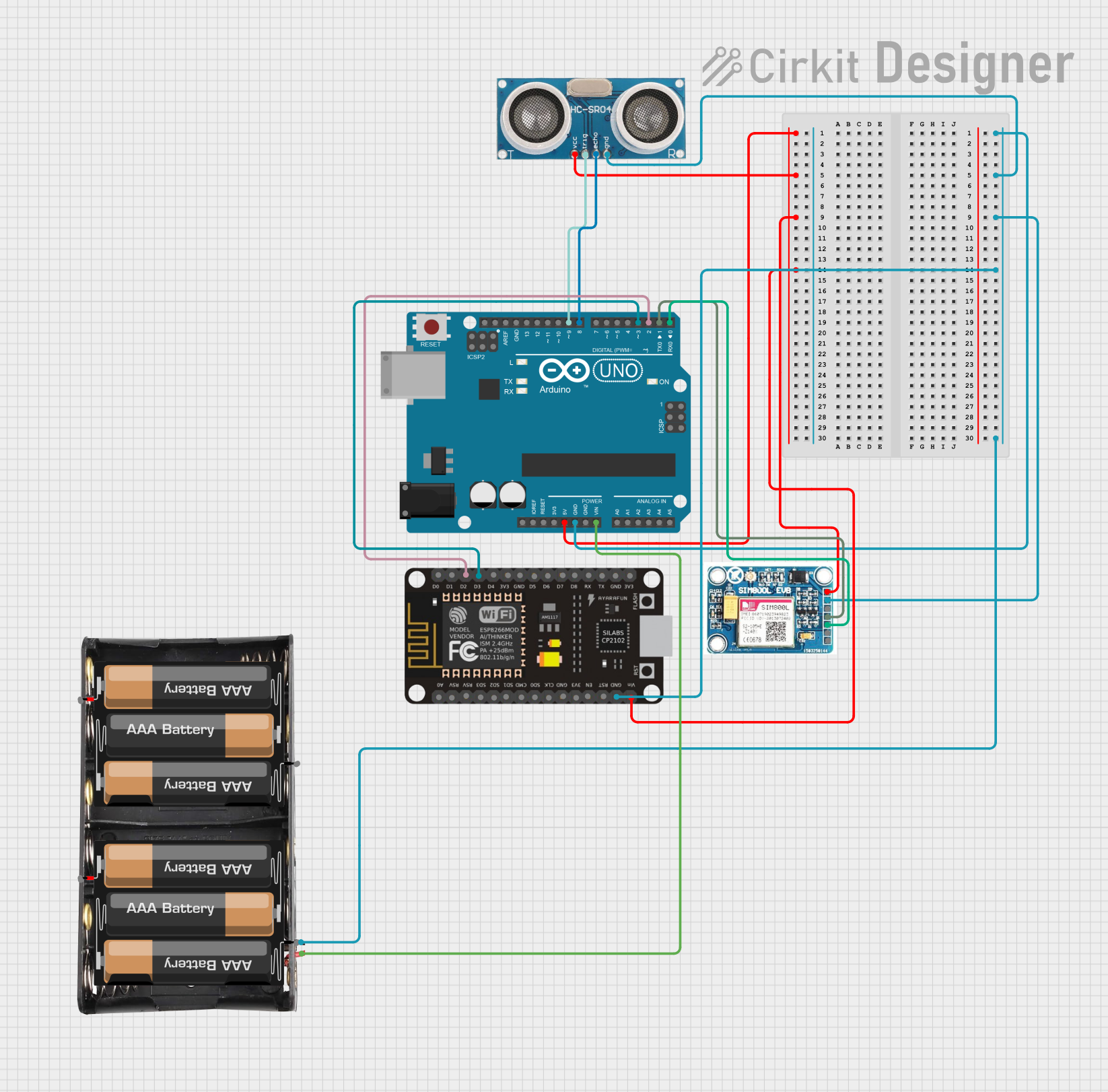
Example: Connecting EC200U GSM to Arduino UNO
Below is an example of how to connect the EC200U GSM module to an Arduino UNO and send an SMS.
Wiring Diagram
| EC200U GSM Pin | Arduino UNO Pin |
|---|---|
| VCC | 5V |
| GND | GND |
| TXD | Pin 10 (RX) |
| RXD | Pin 11 (TX) |
Arduino Code
#include <SoftwareSerial.h>

// Define RX and TX pins for SoftwareSerial
SoftwareSerial gsmSerial(10, 11); // RX = Pin 10, TX = Pin 11

void setup() {
  // Initialize serial communication with GSM module
  gsmSerial.begin(9600); // Set baud rate to 9600
  Serial.begin(9600);    // Initialize Serial Monitor

  // Wait for the module to initialize
  delay(1000);
  Serial.println("Initializing GSM module...");

  // Send AT command to check communication
  gsmSerial.println("AT");
  delay(1000);
  while (gsmSerial.available()) {
    Serial.write(gsmSerial.read()); // Print GSM module response
  }

  // Send SMS command
  gsmSerial.println("AT+CMGF=1"); // Set SMS mode to text
  delay(1000);
  gsmSerial.println("AT+CMGS=\"+1234567890\""); // Replace with recipient's number
  delay(1000);
  gsmSerial.print("Hello from EC200U GSM!"); // SMS content
  delay(1000);
  gsmSerial.write(26); // Send Ctrl+Z to send the SMS
  Serial.println("SMS sent!");
}

void loop() {
  // Continuously check for incoming data from GSM module
  if (gsmSerial.available()) {
    Serial.write(gsmSerial.read());
  }
}
Troubleshooting and FAQs
Common Issues and Solutions
No Response from the Module
- Cause: Incorrect wiring or baud rate mismatch.
- Solution: Double-check the connections and ensure the baud rate matches the module's default setting (9600).
SIM Card Not Detected
- Cause: Improper SIM card insertion or incompatible SIM card.
- Solution: Ensure the SIM card is properly seated and supports 1.8V/3.0V operation.
Weak or No Signal
- Cause: Poor antenna placement or low network coverage.
- Solution: Reposition the antenna or move to an area with better network coverage.
Module Overheating
- Cause: Excessive power supply voltage or prolonged high current draw.
- Solution: Ensure the power supply voltage is within the specified range and use a heatsink if necessary.
FAQs
Q: Can the EC200U GSM module work with 4G networks?
A: No, the EC200U GSM module supports 2G/3G networks only.Q: What is the maximum length of an SMS that can be sent?
A: The maximum length of a single SMS is 160 characters. For longer messages, use concatenated SMS.Q: Can I use the module without a SIM card?
A: No, a SIM card is required for network registration and communication.Q: How do I update the firmware of the EC200U GSM module?
A: Firmware updates can be performed via the USB interface using the manufacturer's tools and instructions.