
How to Use MyoWare Power Shield: Examples, Pinouts, and Specs
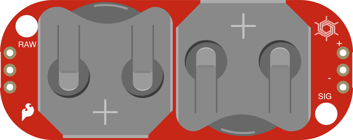
 Design with MyoWare Power Shield in Cirkit Designer
Introduction
The MyoWare Power Shield (Manufacturer Part ID: DEV-13684) is a power management board designed by SparkFun Electronics. It provides a stable and reliable power supply for MyoWare muscle sensors, ensuring optimal performance. The shield features onboard voltage regulation and is designed for seamless integration with microcontrollers, such as Arduino boards. Its compact design and ease of use make it an essential accessory for biofeedback and muscle-sensing projects.
Explore Projects Built with MyoWare Power Shield
 Open Project in Cirkit Designer
 Open Project in Cirkit Designer
 Open Project in Cirkit Designer
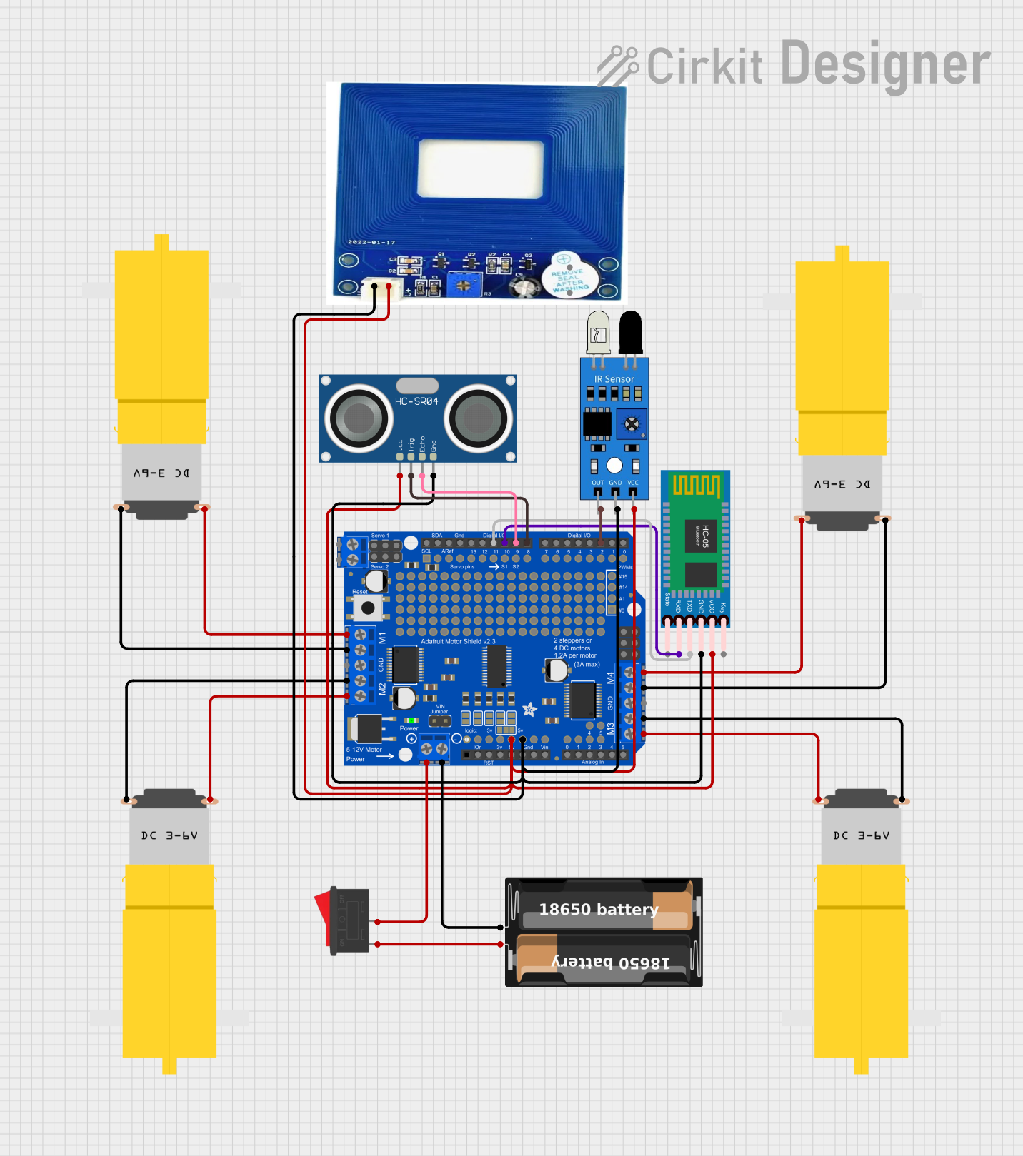 Open Project in Cirkit Designer
Explore Projects Built with MyoWare Power Shield
Open Project in Cirkit DesignerOpen Project in Cirkit DesignerOpen Project in Cirkit DesignerOpen Project in Cirkit DesignerCommon Applications and Use Cases
- Powering MyoWare muscle sensors in wearable devices
- Biofeedback systems for medical or fitness applications
- Robotics and prosthetics requiring muscle signal inputs
- Educational projects involving electromyography (EMG) sensors
Technical Specifications
The MyoWare Power Shield is engineered to simplify power management for MyoWare sensors. Below are its key technical details:
Key Technical Details
| Parameter | Specification |
|---|---|
| Input Voltage Range | 3.3V to 5.0V |
| Output Voltage | 3.3V (regulated) |
| Maximum Output Current | 40mA |
| Connector Type | JST PH (2-pin) for power input |
| Dimensions | 1.0" x 1.0" (25.4mm x 25.4mm) |
| Weight | 2.5g |
Pin Configuration and Descriptions
The MyoWare Power Shield features a simple pin layout for easy integration:
| Pin Name | Description |
|---|---|
| VIN | Power input pin (3.3V to 5.0V). Connect to an external power source. |
| GND | Ground pin. Connect to the ground of your circuit. |
| VOUT | Regulated 3.3V output pin. Provides stable power to MyoWare muscle sensors. |
| ON/OFF Switch | Toggle switch to enable or disable power output. |
Usage Instructions
The MyoWare Power Shield is designed for straightforward use with MyoWare muscle sensors and microcontrollers. Follow the steps below to integrate it into your project:
How to Use the Component in a Circuit
Connect Power Input:
- Use a JST PH (2-pin) cable to connect a 3.3V to 5.0V power source to the VIN and GND pins of the shield.
- Alternatively, you can solder wires directly to the VIN and GND pads.
Connect to MyoWare Sensor:
- Attach the MyoWare muscle sensor to the VOUT and GND pins of the shield. This provides the sensor with a stable 3.3V power supply.
Enable Power Output:
- Slide the ON/OFF switch to the "ON" position to enable the regulated 3.3V output.
Integrate with a Microcontroller:
- If using an Arduino or other microcontroller, connect the MyoWare sensor's signal output to an analog input pin on the microcontroller.
Important Considerations and Best Practices
- Power Source Selection: Ensure the input voltage is within the 3.3V to 5.0V range to avoid damaging the shield or connected components.
- Current Limitations: The shield can supply a maximum of 40mA. Avoid connecting devices that exceed this current draw.
- Proper Connections: Double-check all connections before powering the shield to prevent short circuits or incorrect wiring.
- Switch Position: Always turn the power switch off when making or modifying connections.
Example Arduino Code
Below is an example of how to read data from a MyoWare muscle sensor connected to an Arduino UNO:
// Example code to read MyoWare muscle sensor data using Arduino UNO

const int myoWarePin = A0; // Analog pin connected to MyoWare sensor output

void setup() {
  Serial.begin(9600); // Initialize serial communication at 9600 baud
  pinMode(myoWarePin, INPUT); // Set the MyoWare pin as an input
}

void loop() {
  int sensorValue = analogRead(myoWarePin); // Read the analog value from the sensor
  Serial.print("Muscle Sensor Value: "); // Print a label for the sensor value
  Serial.println(sensorValue); // Print the sensor value to the Serial Monitor
  delay(100); // Delay for 100ms to avoid flooding the Serial Monitor
}
Troubleshooting and FAQs
Common Issues and Solutions
No Power Output:
- Cause: The ON/OFF switch is in the "OFF" position.
- Solution: Slide the switch to the "ON" position to enable power output.
Sensor Not Working:
- Cause: Incorrect wiring or insufficient power supply.
- Solution: Verify all connections and ensure the input voltage is within the specified range (3.3V to 5.0V).
Microcontroller Not Reading Data:
- Cause: Signal pin not connected to the correct analog input.
- Solution: Check the wiring and ensure the signal pin is connected to an analog input pin on the microcontroller.
Overheating:
- Cause: Excessive current draw from connected devices.
- Solution: Ensure the total current draw does not exceed 40mA.
FAQs
Q1: Can I use a battery to power the MyoWare Power Shield?
A1: Yes, you can use a 3.7V LiPo battery or any other power source within the 3.3V to 5.0V range.
Q2: Is the MyoWare Power Shield compatible with all MyoWare sensors?
A2: Yes, the shield is designed to work seamlessly with all MyoWare muscle sensors.
Q3: Can I use the shield to power other devices besides MyoWare sensors?
A3: While the shield is optimized for MyoWare sensors, it can power other low-current devices requiring 3.3V, as long as the total current draw does not exceed 40mA.
Q4: What happens if I exceed the maximum current rating?
A4: Exceeding the 40mA limit may cause the shield to overheat or fail. Always ensure connected devices stay within the specified current range.