How to Use CL42T Stepper Motor Driver: Examples, Pinouts, and Specs
Introduction
The CL42T Stepper Motor Driver by Stepper Online is a compact and efficient driver designed to control stepper motors with precision. It enables smooth motion and accurate positioning, making it ideal for applications requiring high reliability and performance. This driver is compatible with a wide range of stepper motors and is suitable for use in CNC machines, 3D printers, robotics, and other motion control systems.
Explore Projects Built with CL42T Stepper Motor Driver


Explore Projects Built with CL42T Stepper Motor Driver
Common Applications
- CNC machines for precise cutting and milling
- 3D printers for accurate layer deposition
- Robotics for controlled movement and positioning
- Conveyor systems in industrial automation
- Camera sliders and gimbals for smooth motion control
Technical Specifications
The following table outlines the key technical details of the CL42T Stepper Motor Driver:
| Parameter | Value |
|---|---|
| Manufacturer Part ID | CL42T |
| Input Voltage Range | 20V - 50V DC |
| Output Current Range | 1.0A - 4.2A (adjustable) |
| Microstepping Resolution | Up to 256 microsteps |
| Control Signal Type | Pulse/Direction or CW/CCW |
| Logic Signal Voltage | 3.3V - 24V |
| Operating Temperature | -10°C to +45°C |
| Dimensions | 118mm x 75mm x 34mm |
| Weight | 300g |
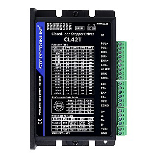
Pin Configuration and Descriptions
The CL42T features a set of input and output terminals for easy integration into your system. Below is the pin configuration:
Input Signal Terminals
| Pin | Name | Description |
|---|---|---|
| 1 | PUL+ | Positive terminal for pulse signal input |
| 2 | PUL- | Negative terminal for pulse signal input |
| 3 | DIR+ | Positive terminal for direction signal input |
| 4 | DIR- | Negative terminal for direction signal input |
| 5 | ENA+ | Positive terminal for enable signal input (optional, for motor activation) |
| 6 | ENA- | Negative terminal for enable signal input (optional, for motor activation) |
Power and Motor Terminals
| Pin | Name | Description |
|---|---|---|
| 1 | V+ | Positive terminal for DC power supply (20V - 50V) |
| 2 | V- | Negative terminal for DC power supply |
| 3 | A+ | Positive terminal for stepper motor coil A |
| 4 | A- | Negative terminal for stepper motor coil A |
| 5 | B+ | Positive terminal for stepper motor coil B |
| 6 | B- | Negative terminal for stepper motor coil B |
Usage Instructions
Connecting the CL42T to a Stepper Motor
- Power Supply: Connect a DC power supply (20V - 50V) to the V+ and V- terminals. Ensure the power supply can provide sufficient current for your motor.
- Motor Connection: Connect the stepper motor coils to the A+/A- and B+/B- terminals. Refer to your motor's datasheet to identify the correct coil pairs.
- Control Signals: Connect the PUL+, PUL-, DIR+, DIR-, and (optionally) ENA+ and ENA- terminals to your controller (e.g., Arduino, CNC controller).
- Microstepping and Current Settings: Use the DIP switches on the driver to configure the microstepping resolution and output current. Refer to the driver’s user manual for detailed DIP switch settings.
Important Considerations
- Current Setting: Set the output current to match your stepper motor's rated current. Overdriving the motor can cause overheating or damage.
- Signal Voltage: Ensure the control signal voltage (3.3V - 24V) matches the driver’s input requirements.
- Cooling: Install the driver in a well-ventilated area to prevent overheating. Use a heatsink or fan if necessary.
- Wiring: Double-check all connections before powering on the system to avoid short circuits or damage.
Example: Using CL42T with Arduino UNO
Below is an example of how to control the CL42T with an Arduino UNO:
Wiring Diagram
- PUL+: Connect to Arduino digital pin 3
- PUL-: Connect to Arduino GND
- DIR+: Connect to Arduino digital pin 4
- DIR-: Connect to Arduino GND
- ENA+: Connect to Arduino digital pin 5 (optional)
- ENA-: Connect to Arduino GND
Arduino Code
// Define pins for the CL42T Stepper Motor Driver
#define PUL_PIN 3  // Pulse signal pin
#define DIR_PIN 4  // Direction signal pin
#define ENA_PIN 5  // Enable signal pin (optional)

void setup() {
  // Set pin modes
  pinMode(PUL_PIN, OUTPUT);
  pinMode(DIR_PIN, OUTPUT);
  pinMode(ENA_PIN, OUTPUT);

  // Enable the driver
  digitalWrite(ENA_PIN, LOW); // LOW to enable the driver
}

void loop() {
  // Set direction
  digitalWrite(DIR_PIN, HIGH); // HIGH for one direction, LOW for the other

  // Generate pulses to move the motor
  for (int i = 0; i < 200; i++) { // 200 steps for one revolution (example)
    digitalWrite(PUL_PIN, HIGH);
    delayMicroseconds(500); // Adjust for speed
    digitalWrite(PUL_PIN, LOW);
    delayMicroseconds(500); // Adjust for speed
  }

  delay(1000); // Wait 1 second before reversing direction

  // Reverse direction
  digitalWrite(DIR_PIN, LOW);

  // Generate pulses to move the motor in the opposite direction
  for (int i = 0; i < 200; i++) {
    digitalWrite(PUL_PIN, HIGH);
    delayMicroseconds(500);
    digitalWrite(PUL_PIN, LOW);
    delayMicroseconds(500);
  }

  delay(1000); // Wait 1 second before repeating
}
Troubleshooting and FAQs
Common Issues
Motor Not Moving
- Check the power supply voltage and ensure it is within the 20V - 50V range.
- Verify the motor connections (A+/A-, B+/B-) and ensure they match the motor's coil pairs.
- Ensure the control signals (PUL, DIR, ENA) are correctly connected and configured.
Motor Vibrates but Does Not Rotate
- Check the microstepping and current settings on the DIP switches.
- Verify the pulse signal frequency and ensure it matches the motor's requirements.
Driver Overheating
- Ensure proper ventilation and consider adding a heatsink or fan.
- Verify that the output current is not set higher than the motor's rated current.
FAQs
Q: Can I use the CL42T with a 12V power supply?
A: No, the CL42T requires a minimum input voltage of 20V. Using a 12V supply will not power the driver correctly.
Q: What is the maximum step frequency supported by the CL42T?
A: The CL42T supports a maximum pulse frequency of 200 kHz.
Q: Can I use the CL42T with a NEMA 23 stepper motor?
A: Yes, the CL42T is compatible with NEMA 23 stepper motors, provided the motor's current rating is within the driver's range (1.0A - 4.2A).
Q: How do I reset the driver after a fault?
A: Power off the driver, check for the cause of the fault (e.g., overcurrent, overheating), and resolve the issue before powering it back on.