How to Use DRV8871: Examples, Pinouts, and Specs
Introduction
The DRV8871 is a versatile H-bridge DC motor driver IC designed for driving DC motors and stepper motors. It supports bidirectional motor control, making it ideal for applications requiring forward and reverse motor operation. The DRV8871 is equipped with built-in protection features, including overcurrent protection, thermal shutdown, and undervoltage lockout, ensuring reliable operation in various environments.
Explore Projects Built with DRV8871

Explore Projects Built with DRV8871
Common Applications
- Robotics and automation systems
- Electric door locks and actuators
- Conveyor belts and industrial machinery
- Consumer electronics with motorized components
- Educational projects involving motor control
Technical Specifications
Key Technical Details
| Parameter | Value |
|---|---|
| Supply Voltage (Vcc) | 6.5V to 45V |
| Output Current (Iout) | Up to 3.6A (continuous) |
| Peak Current | 6A (for short durations) |
| Logic Input Voltage | 0V to 5.5V |
| PWM Frequency | Up to 100 kHz |
| Operating Temperature | -40°C to 125°C |
| Built-in Protections | Overcurrent, thermal shutdown, undervoltage lockout |
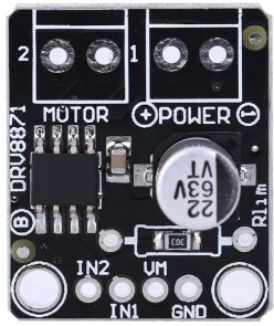
Pin Configuration and Descriptions
The DRV8871 is available in an 8-pin package. Below is the pinout and description:
| Pin Number | Pin Name | Description |
|---|---|---|
| 1 | IN1 | Logic input 1 for controlling motor direction and speed. |
| 2 | IN2 | Logic input 2 for controlling motor direction and speed. |
| 3 | nFAULT | Fault indicator output (active low). |
| 4 | GND | Ground connection. |
| 5 | OUT1 | Motor output terminal 1. |
| 6 | OUT2 | Motor output terminal 2. |
| 7 | Vcc | Power supply input (6.5V to 45V). |
| 8 | nSLEEP | Sleep mode input (active low). Pull high to enable the device. |
Usage Instructions
Using the DRV8871 in a Circuit
- Power Supply: Connect the Vcc pin to a power supply within the range of 6.5V to 45V. Ensure the power supply can provide sufficient current for the motor.
- Motor Connections: Connect the motor terminals to the OUT1 and OUT2 pins.
- Logic Inputs: Use the IN1 and IN2 pins to control the motor's direction and speed:
- Apply a PWM signal to either IN1 or IN2 for speed control.
- Set IN1 high and IN2 low for forward rotation.
- Set IN1 low and IN2 high for reverse rotation.
- Set both IN1 and IN2 low to stop the motor.
- Fault Monitoring: Monitor the nFAULT pin for any fault conditions. If the pin is pulled low, check for overcurrent or thermal shutdown.
- Sleep Mode: Pull the nSLEEP pin high to enable the device. Pull it low to put the device into low-power sleep mode.
Important Considerations
- Use appropriate decoupling capacitors (e.g., 0.1 µF and 10 µF) near the Vcc pin to stabilize the power supply.
- Ensure the motor's current rating does not exceed the DRV8871's maximum continuous current of 3.6A.
- Use a heatsink or proper ventilation if operating near the maximum current to prevent thermal shutdown.
- Avoid floating logic inputs; always pull them high or low.
Example: Connecting the DRV8871 to an Arduino UNO
Below is an example of how to control a DC motor using the DRV8871 and an Arduino UNO:
Circuit Connections
- DRV8871 IN1 → Arduino Digital Pin 9
- DRV8871 IN2 → Arduino Digital Pin 10
- DRV8871 nSLEEP → Arduino Digital Pin 8
- DRV8871 Vcc → Motor power supply (e.g., 12V)
- DRV8871 GND → Common ground with Arduino and power supply
- Motor Terminals → DRV8871 OUT1 and OUT2
Arduino Code
// DRV8871 Motor Driver Example Code
// Controls motor direction and speed using PWM signals

#define IN1 9       // IN1 connected to Arduino pin 9
#define IN2 10      // IN2 connected to Arduino pin 10
#define nSLEEP 8    // nSLEEP connected to Arduino pin 8

void setup() {
  pinMode(IN1, OUTPUT);    // Set IN1 as output
  pinMode(IN2, OUTPUT);    // Set IN2 as output
  pinMode(nSLEEP, OUTPUT); // Set nSLEEP as output

  digitalWrite(nSLEEP, HIGH); // Enable the DRV8871
}

void loop() {
  // Forward rotation at 50% speed
  analogWrite(IN1, 128);   // PWM signal (50% duty cycle)
  digitalWrite(IN2, LOW);  // IN2 low
  delay(2000);             // Run for 2 seconds

  // Reverse rotation at 75% speed
  digitalWrite(IN1, LOW);  // IN1 low
  analogWrite(IN2, 192);   // PWM signal (75% duty cycle)
  delay(2000);             // Run for 2 seconds

  // Stop the motor
  digitalWrite(IN1, LOW);  // IN1 low
  digitalWrite(IN2, LOW);  // IN2 low
  delay(2000);             // Stop for 2 seconds
}
Troubleshooting and FAQs
Common Issues and Solutions
Motor Not Spinning
- Cause: nSLEEP pin is low.
- Solution: Ensure the nSLEEP pin is pulled high to enable the device.
- Cause: Incorrect logic input configuration.
- Solution: Verify the IN1 and IN2 signals are set correctly for the desired motor direction.
Motor Spins in the Wrong Direction
- Cause: Motor terminals are reversed.
- Solution: Swap the connections of the motor to OUT1 and OUT2.
nFAULT Pin is Low
- Cause: Overcurrent or thermal shutdown.
- Solution: Check the motor's current draw and ensure it does not exceed 3.6A. Allow the device to cool down if it has overheated.
Excessive Heat
- Cause: High current operation without proper cooling.
- Solution: Use a heatsink or improve ventilation around the DRV8871.
FAQs
Can the DRV8871 drive stepper motors? Yes, the DRV8871 can drive stepper motors in a unipolar or bipolar configuration. However, additional control logic is required for stepper motor operation.
What is the maximum PWM frequency supported? The DRV8871 supports PWM frequencies up to 100 kHz.
Is it necessary to use external diodes for motor protection? No, the DRV8871 has built-in flyback diodes for motor protection.
Can I use the DRV8871 with a 3.3V microcontroller? Yes, the logic inputs are compatible with 3.3V and 5V systems.