How to Use MH-ET Live Scanner: Examples, Pinouts, and Specs
Introduction
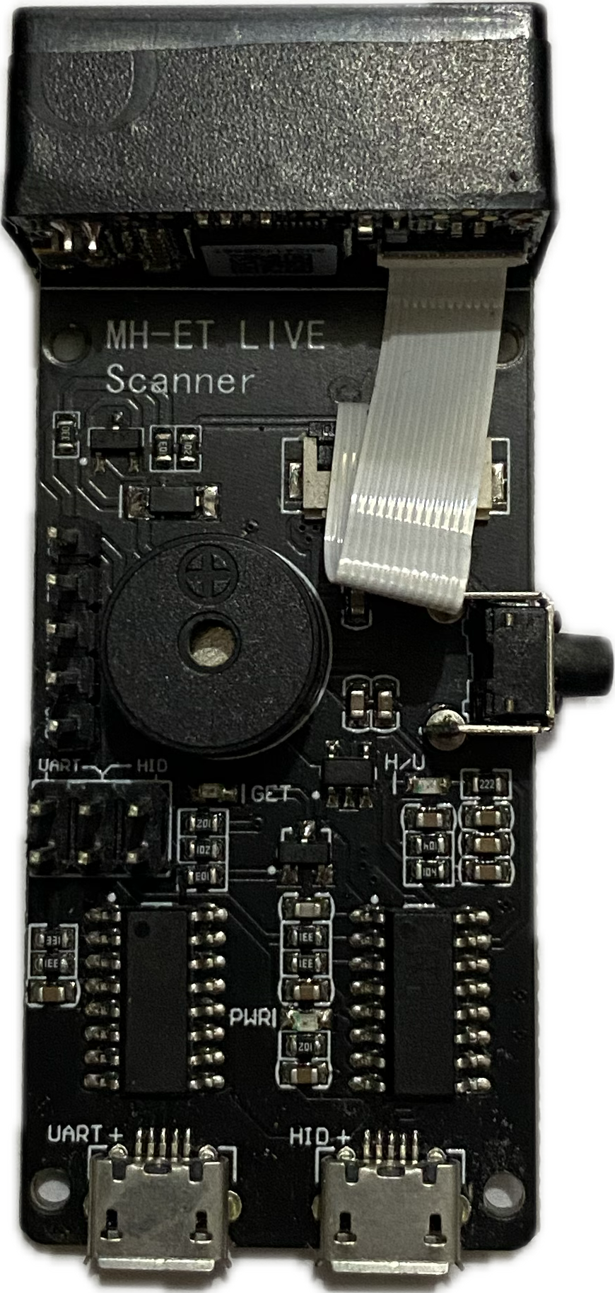
The MH-ET Live Scanner is a compact and versatile device designed for real-time monitoring and analysis of electrical signals in circuits. It is widely used for troubleshooting and diagnostics in various electronic applications. This component is particularly useful for detecting signal patterns, voltage levels, and other electrical characteristics, making it an essential tool for engineers, hobbyists, and students working on electronic projects.
Explore Projects Built with MH-ET Live Scanner
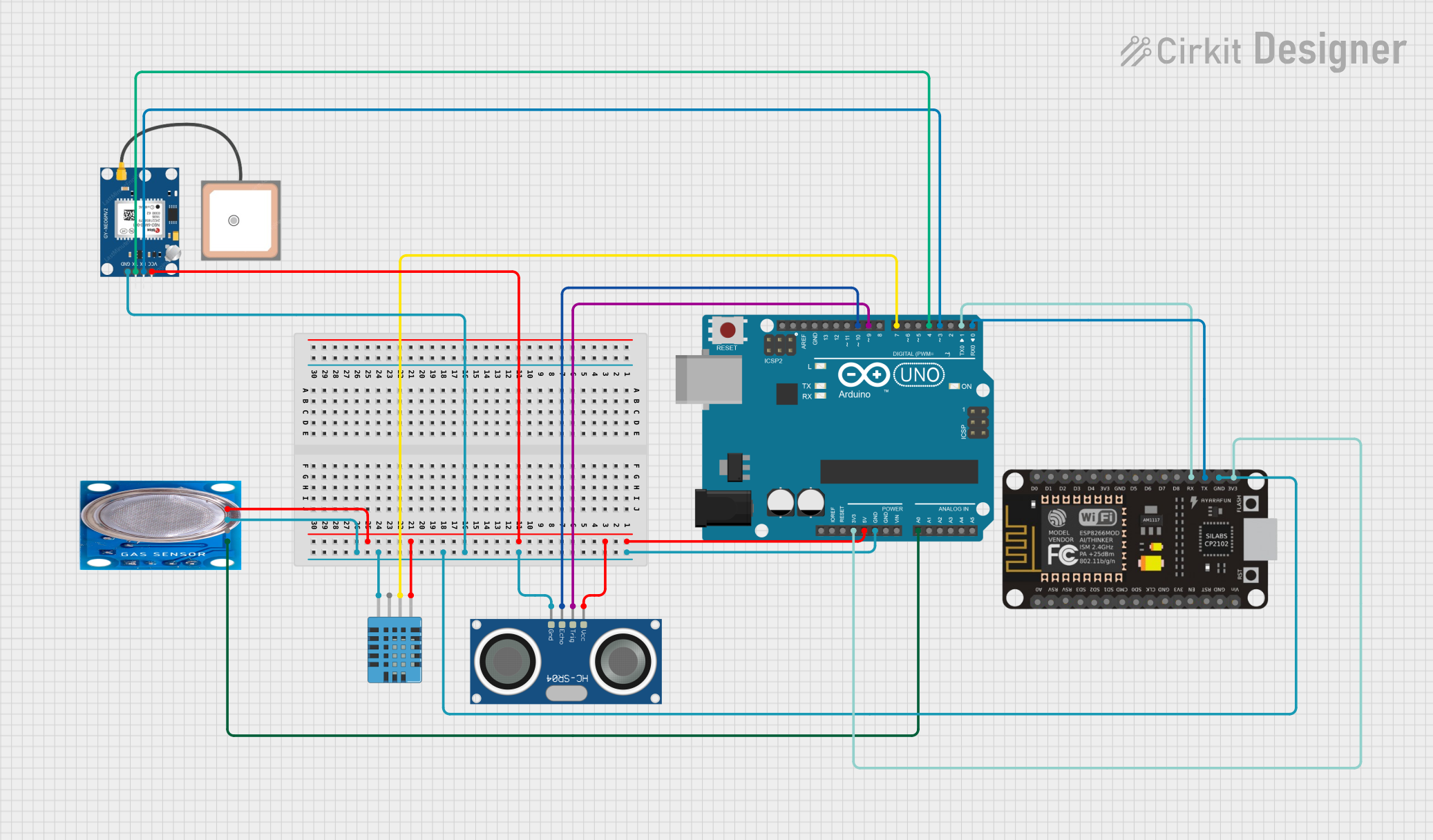
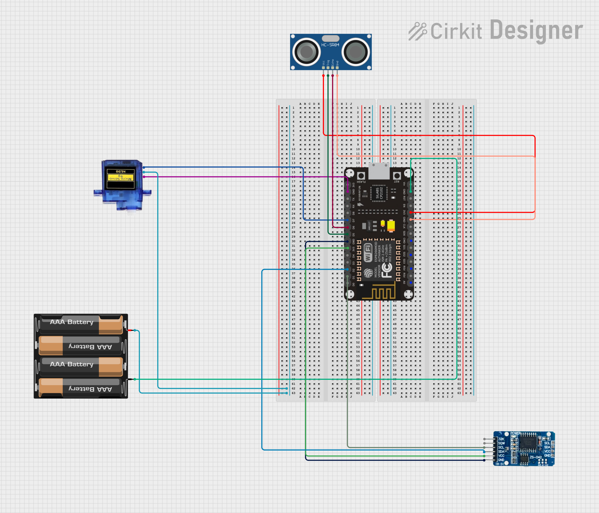
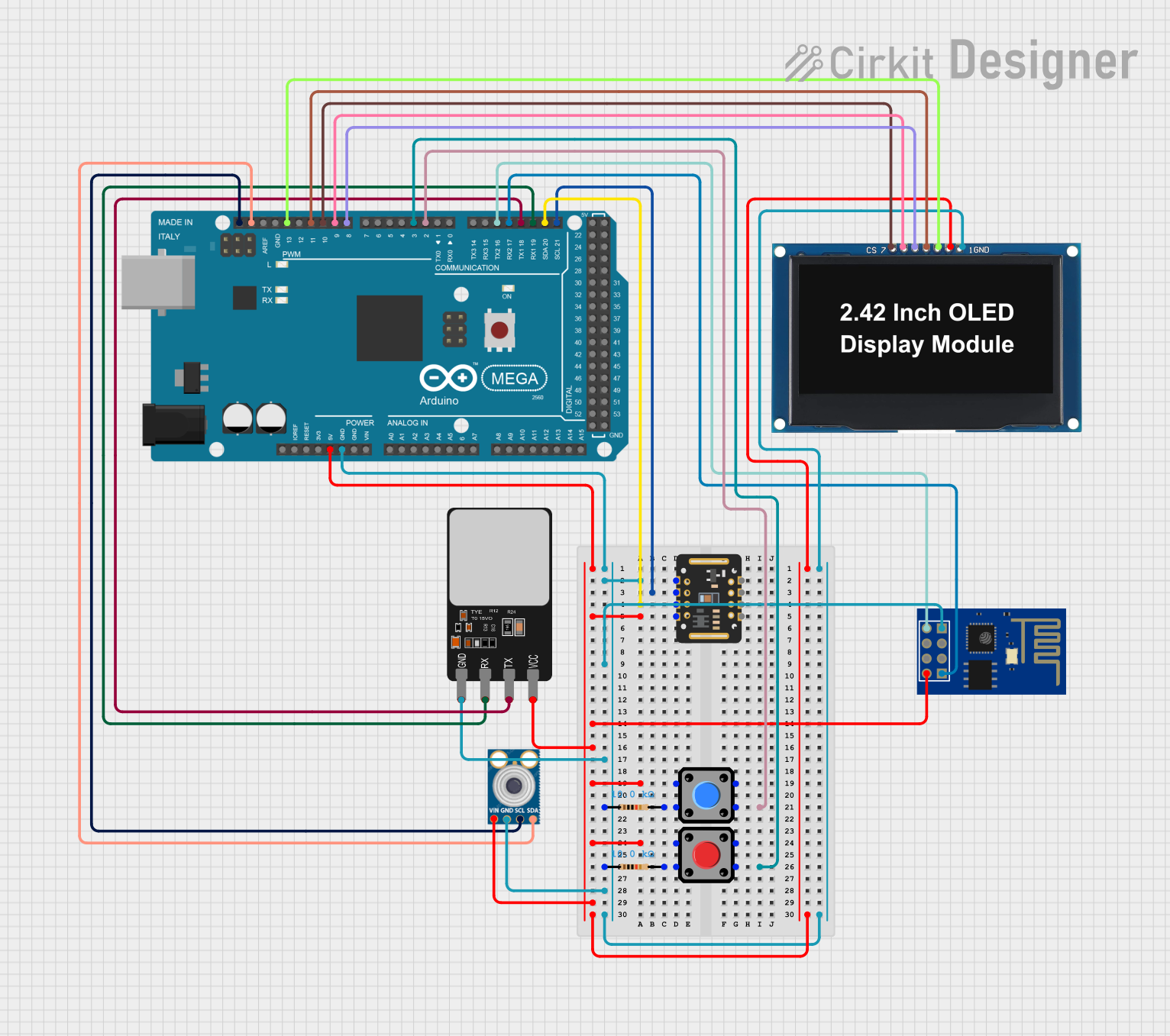
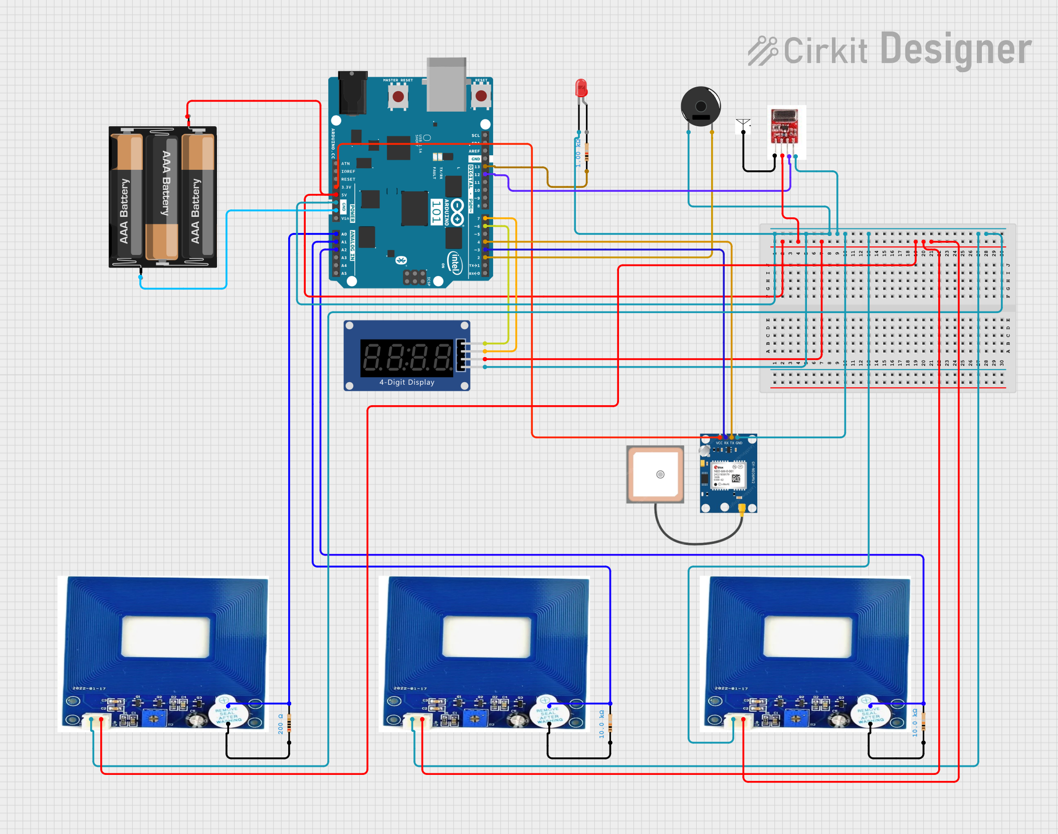
Explore Projects Built with MH-ET Live Scanner
Common Applications and Use Cases
- Debugging and troubleshooting electronic circuits
- Monitoring signal integrity in real-time
- Analyzing voltage levels and waveforms
- Educational purposes for learning circuit behavior
- Integration into test benches for automated diagnostics
Technical Specifications
The MH-ET Live Scanner is designed to be user-friendly while offering robust performance. Below are its key technical specifications:
General Specifications
| Parameter | Value |
|---|---|
| Operating Voltage | 3.3V to 5V |
| Current Consumption | < 50mA |
| Signal Input Range | 0V to 5V |
| Display Type | LED bar graph |
| Number of LEDs | 10 |
| Response Time | < 1ms |
| Dimensions | 50mm x 20mm x 10mm |
Pin Configuration and Descriptions
| Pin Name | Pin Number | Description |
|---|---|---|
| VCC | 1 | Power supply input (3.3V to 5V) |
| GND | 2 | Ground connection |
| SIG | 3 | Signal input for monitoring |
| EN | 4 | Enable pin (active HIGH to activate the scanner) |
Usage Instructions
The MH-ET Live Scanner is straightforward to use and can be integrated into a variety of circuits. Follow the steps below to use the component effectively:
Connecting the MH-ET Live Scanner
- Power Supply: Connect the
VCCpin to a 3.3V or 5V power source and theGNDpin to the ground of your circuit. - Signal Input: Connect the
SIGpin to the signal line you want to monitor. Ensure the signal voltage does not exceed 5V. - Enable the Scanner: If the
ENpin is available, set it HIGH to activate the scanner. If not connected, the scanner is enabled by default.
Important Considerations
- Signal Voltage Range: Ensure the input signal voltage is within the 0V to 5V range to avoid damaging the device.
- Power Supply: Use a stable power source to prevent fluctuations in the LED bar graph display.
- Placement: Avoid placing the scanner near high-frequency noise sources to ensure accurate readings.
Example: Using with Arduino UNO
The MH-ET Live Scanner can be easily connected to an Arduino UNO for signal monitoring. Below is an example code snippet:
// Example: Using MH-ET Live Scanner with Arduino UNO
// This code generates a PWM signal on pin 9 and monitors it using the scanner.

const int pwmPin = 9; // PWM output pin
const int enablePin = 7; // Enable pin for the scanner

void setup() {
  pinMode(pwmPin, OUTPUT); // Set PWM pin as output
  pinMode(enablePin, OUTPUT); // Set enable pin as output

  digitalWrite(enablePin, HIGH); // Enable the scanner
}

void loop() {
  // Generate a PWM signal with 50% duty cycle
  analogWrite(pwmPin, 128); // 128 corresponds to 50% duty cycle (0-255 range)

  // The scanner will display the signal level in real-time
  delay(100); // Small delay for stability
}
Best Practices
- Use short and direct connections to minimize signal loss or interference.
- If monitoring high-frequency signals, ensure proper grounding and shielding of the circuit.
- Regularly check the connections to avoid loose wires or poor contact.
Troubleshooting and FAQs
Common Issues and Solutions
| Issue | Possible Cause | Solution |
|---|---|---|
| LEDs do not light up | No power or incorrect wiring | Check VCC and GND connections. |
| LEDs flicker or display unstable | Unstable power supply or noisy signal | Use a stable power source and filter noise. |
| Signal not displayed correctly | Signal voltage out of range | Ensure signal voltage is between 0V and 5V. |
| Scanner does not activate | EN pin not set HIGH |
Set the EN pin HIGH or leave it unconnected. |
FAQs
Can the MH-ET Live Scanner handle AC signals?
- No, the scanner is designed for DC signals within the 0V to 5V range. For AC signals, use a rectifier circuit to convert them to DC.
What happens if the input signal exceeds 5V?
- Input signals above 5V can damage the scanner. Use a voltage divider or level shifter to step down the signal.
Can I use the scanner with a 3.3V microcontroller?
- Yes, the scanner is compatible with both 3.3V and 5V systems.
How do I interpret the LED bar graph?
- Each LED represents a specific voltage level. The more LEDs lit, the higher the signal voltage.
By following this documentation, you can effectively use the MH-ET Live Scanner for real-time signal monitoring and diagnostics in your electronic projects.