How to Use DC to DC stepdown module : Examples, Pinouts, and Specs
Introduction
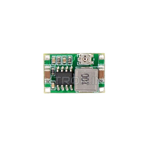
A DC to DC stepdown module, also known as a buck converter, is a power converter designed to reduce a higher DC voltage to a lower DC voltage while maintaining high efficiency. This module is widely used in electronic circuits to power devices that require a specific lower voltage from a higher voltage source, such as batteries, solar panels, or power supplies. Its compact size, efficiency, and reliability make it an essential component in various applications.
Explore Projects Built with DC to DC stepdown module


Explore Projects Built with DC to DC stepdown module
Common Applications and Use Cases
- Powering microcontrollers (e.g., Arduino, Raspberry Pi) from higher voltage sources
- Voltage regulation in battery-powered devices
- Stepdown conversion for LED drivers
- Powering sensors and modules in embedded systems
- Automotive electronics for reducing car battery voltage to power accessories
Technical Specifications
Below are the general technical specifications for a typical DC to DC stepdown module. Note that specific models may vary, so always refer to the datasheet of your module for exact details.
Key Technical Details
- Input Voltage Range: 4.5V to 40V DC (varies by model)
- Output Voltage Range: Adjustable, typically 1.25V to 37V DC
- Output Current: Up to 3A (depending on the module)
- Efficiency: Up to 92% (varies with input/output voltage and load)
- Switching Frequency: 150 kHz (typical)
- Operating Temperature: -40°C to +85°C
- Protection Features: Overcurrent, overtemperature, and short-circuit protection
Pin Configuration and Descriptions
The module typically has four pins or terminals for input and output connections. Below is a table describing the pin configuration:
| Pin/Terminal | Label | Description |
|---|---|---|
| 1 | VIN | Positive input voltage (connect to power source) |
| 2 | GND | Ground (common ground for input and output) |
| 3 | VOUT | Positive output voltage (connect to load) |
| 4 | ADJ | Voltage adjustment (via potentiometer or resistor) |
Note: Some modules may not have a separate ADJ pin and instead use an onboard potentiometer for voltage adjustment.
Usage Instructions
How to Use the Component in a Circuit
- Connect the Input Voltage:
- Connect the positive terminal of your power source to the
VINpin. - Connect the ground of your power source to the
GNDpin.
- Connect the positive terminal of your power source to the
- Adjust the Output Voltage:
- Use the onboard potentiometer or the
ADJpin to set the desired output voltage. - Measure the output voltage using a multimeter to ensure accuracy.
- Use the onboard potentiometer or the
- Connect the Load:
- Connect the positive terminal of your load to the
VOUTpin. - Connect the ground of your load to the
GNDpin.
- Connect the positive terminal of your load to the
- Power On:
- Turn on the power source and verify that the output voltage matches your requirements.
Important Considerations and Best Practices
- Input Voltage: Ensure the input voltage is within the module's specified range.
- Output Voltage: Do not exceed the maximum output voltage or current rating.
- Heat Dissipation: For high current loads, consider adding a heatsink to the module to prevent overheating.
- Polarity: Double-check the polarity of your connections to avoid damaging the module.
- Load Testing: Test the module with a small load before connecting sensitive devices.
Example: Using with an Arduino UNO
To power an Arduino UNO (operating at 5V) from a 12V battery:
- Connect the 12V battery's positive terminal to
VINand negative terminal toGND. - Adjust the output voltage to 5V using the potentiometer.
- Connect the
VOUTpin to the Arduino's 5V pin andGNDto the Arduino's GND pin.
Here is an example Arduino code to blink an LED while powered by the stepdown module:
// Simple LED blink example for Arduino UNO
// Ensure the stepdown module is set to 5V output before connecting to Arduino

const int ledPin = 13; // Built-in LED pin on Arduino UNO

void setup() {
  pinMode(ledPin, OUTPUT); // Set LED pin as output
}

void loop() {
  digitalWrite(ledPin, HIGH); // Turn the LED on
  delay(1000);               // Wait for 1 second
  digitalWrite(ledPin, LOW);  // Turn the LED off
  delay(1000);               // Wait for 1 second
}
Troubleshooting and FAQs
Common Issues and Solutions
No Output Voltage:
- Check the input voltage and ensure it is within the specified range.
- Verify all connections and ensure proper polarity.
- Inspect the module for physical damage or overheating.
Output Voltage is Incorrect:
- Adjust the potentiometer or resistor connected to the
ADJpin. - Measure the output voltage with a multimeter to confirm the adjustment.
- Adjust the potentiometer or resistor connected to the
Module Overheating:
- Reduce the load current or add a heatsink to the module.
- Ensure proper ventilation around the module.
Load Not Powering On:
- Verify that the load's voltage and current requirements are within the module's output capabilities.
- Check for loose or incorrect connections.
FAQs
Q: Can I use this module to power a 3.3V device?
A: Yes, as long as the module's output voltage is adjustable to 3.3V and the input voltage is within the specified range.
Q: What happens if I reverse the input polarity?
A: Most modules do not have reverse polarity protection, so reversing the input polarity may damage the module. Always double-check your connections.
Q: Can I use this module with a solar panel?
A: Yes, but ensure the solar panel's output voltage and current are within the module's input range. Additionally, consider using a capacitor to stabilize the input voltage.
Q: How do I know if the module is overloaded?
A: If the module overheats or the output voltage drops significantly, it may be overloaded. Reduce the load or use a higher-rated module.
By following this documentation, you can effectively use a DC to DC stepdown module in your projects while ensuring safety and reliability.