How to Use MKE-M04 Potentiometer Module: Examples, Pinouts, and Specs
Introduction
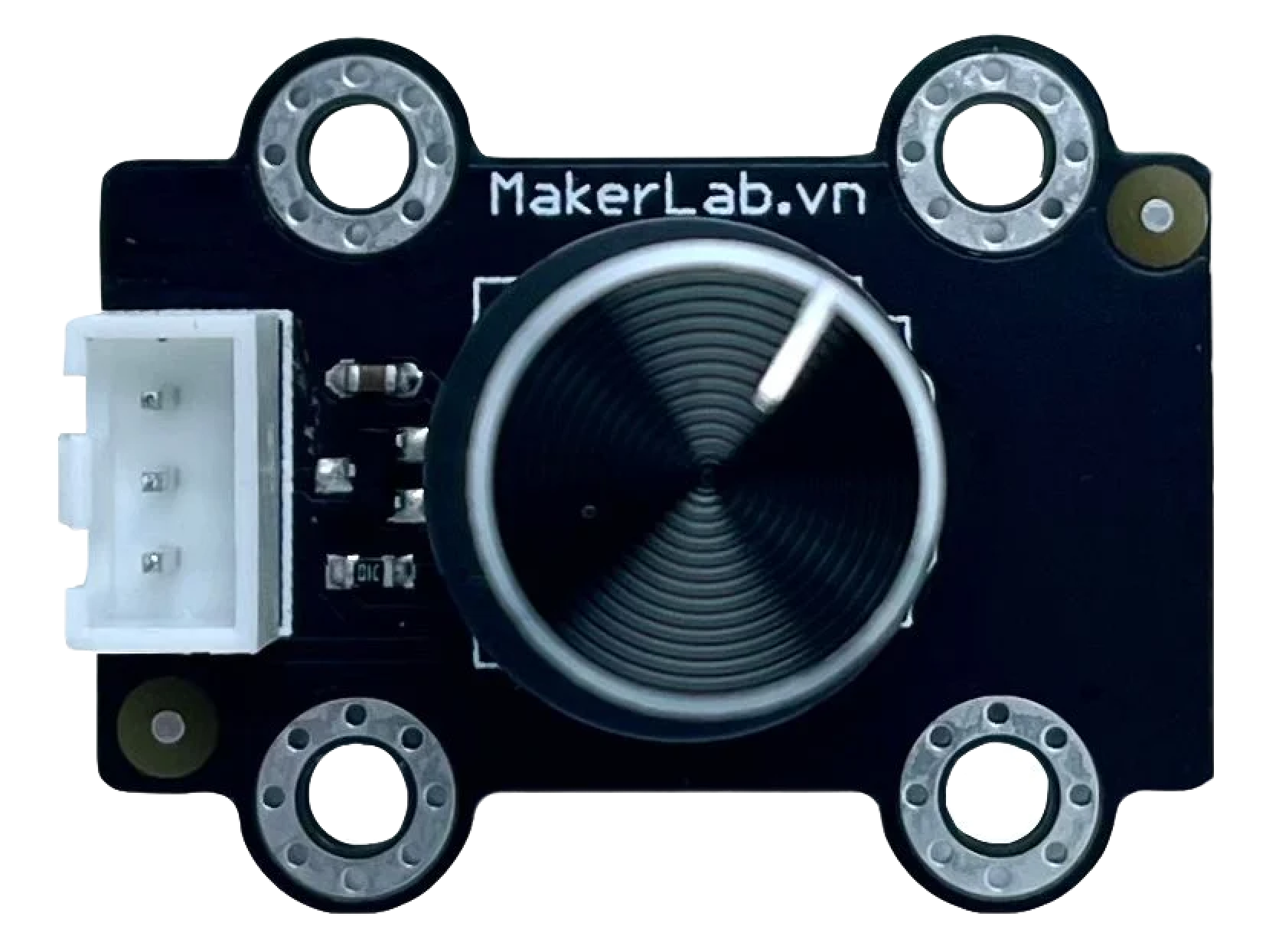
The MKE-M04 Potentiometer Module is an adjustable resistor with a rotary knob, allowing users to vary the output signal within a specific range. This module is widely used in electronics to control variables such as volume, brightness, or motor speed. It is an essential component in projects that require analog input adjustments.
Explore Projects Built with MKE-M04 Potentiometer Module


Explore Projects Built with MKE-M04 Potentiometer Module
Common Applications and Use Cases
- Volume control in audio systems
- Brightness adjustment in lighting systems
- Speed control in motor circuits
- User interface for control panels
Technical Specifications
Key Technical Details
- Resistance Range: Typically 10kΩ
- Tolerance: ±5%
- Power Rating: 0.5W (max)
- Operating Voltage: 0-5V (ideal for use with microcontrollers like Arduino)
- Life Expectancy: 100,000 cycles
Pin Configuration and Descriptions
| Pin Number | Description | Notes |
|---|---|---|
| 1 | VCC (Input Voltage) | Connect to 5V power supply |
| 2 | Signal Output | Analog voltage reflects position |
| 3 | Ground (GND) | Connect to system ground |
Usage Instructions
How to Use the Component in a Circuit
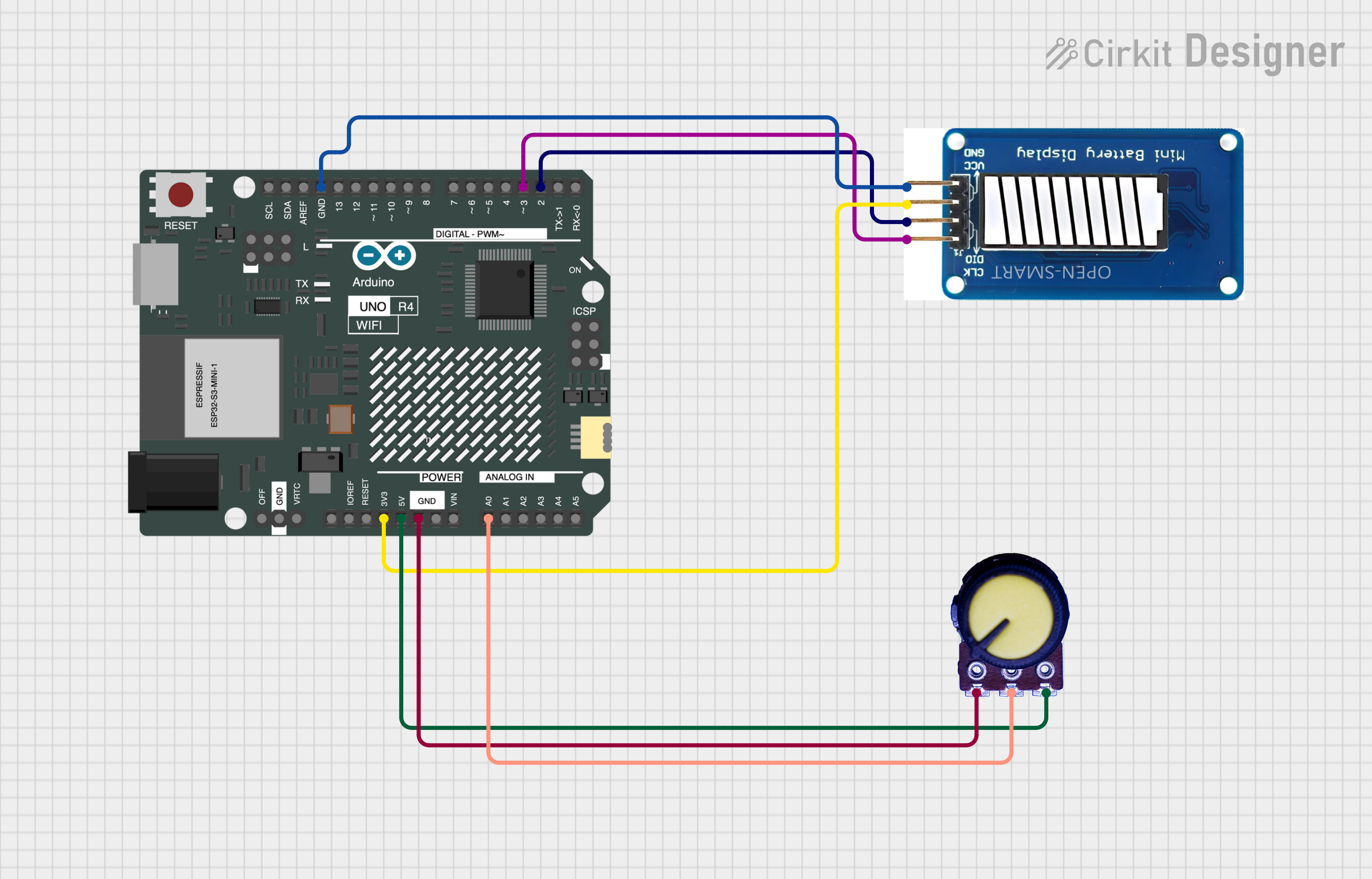
- Connect the VCC pin to a 5V power supply.
- Connect the GND pin to the ground of the power supply.
- Connect the Signal Output pin to an analog input on a microcontroller (e.g., A0 on an Arduino UNO).
Important Considerations and Best Practices
- Do not exceed the maximum power rating of the potentiometer to prevent damage.
- Ensure that the potentiometer is mounted securely to avoid erratic readings.
- Use a pull-down resistor if necessary to ensure a stable zero reference when the potentiometer is at its minimum position.
Example Code for Arduino UNO
// Define the pin where the potentiometer is connected
const int potPin = A0;

void setup() {
  // Initialize serial communication at 9600 bits per second:
  Serial.begin(9600);
}

void loop() {
  // Read the input on analog pin 0:
  int potValue = analogRead(potPin);
  // Convert the analog reading (which goes from 0 - 1023) to a voltage (0 - 5V):
  float voltage = potValue * (5.0 / 1023.0);
  // Print out the value you read:
  Serial.println(voltage);
  delay(100); // Delay a little bit to improve simulation performance
}
Troubleshooting and FAQs
Common Issues Users Might Face
- Erratic Output: Ensure that the potentiometer is not loose and that connections are secure.
- No Output Change: Verify that the potentiometer is not damaged and that it is receiving power.
Solutions and Tips for Troubleshooting
- If you experience unstable readings, consider adding a small capacitor between the signal output and ground to filter noise.
- Always check for proper wiring and soldering if the module is not performing as expected.
- Use a multimeter to check the resistance across the potentiometer terminals to ensure it is functioning correctly.
FAQs
Q: Can I use the MKE-M04 Potentiometer Module with a 3.3V system? A: Yes, the module can be used with a 3.3V system, but the output range will be limited to 0-3.3V.
Q: What is the resolution of the potentiometer module when used with an Arduino? A: The resolution depends on the ADC of the Arduino. For a 10-bit ADC, the resolution is 5V / 1024 steps, which is approximately 4.88mV per step.
Q: How do I calibrate the potentiometer module?
A: Calibration is typically not required for a potentiometer module. However, you can map the output range to your desired range using the map() function in the Arduino IDE.
Q: Can the potentiometer module be used to control AC devices? A: No, the MKE-M04 is designed for DC applications and should not be used to directly control AC devices. Use a relay or a suitable AC controller instead.