
How to Use AD654 - Low Cost Monolithic Voltage-to-Frequency Converter: Examples, Pinouts, and Specs
 Design with AD654 - Low Cost Monolithic Voltage-to-Frequency Converter in Cirkit Designer
Introduction
The AD654 is a precision voltage-to-frequency converter manufactured by Analog Devices. It is designed to convert an analog input voltage into a frequency output that is linearly proportional to the input. This component is widely used in applications requiring high accuracy, low cost, and efficient signal processing.
Explore Projects Built with AD654 - Low Cost Monolithic Voltage-to-Frequency Converter
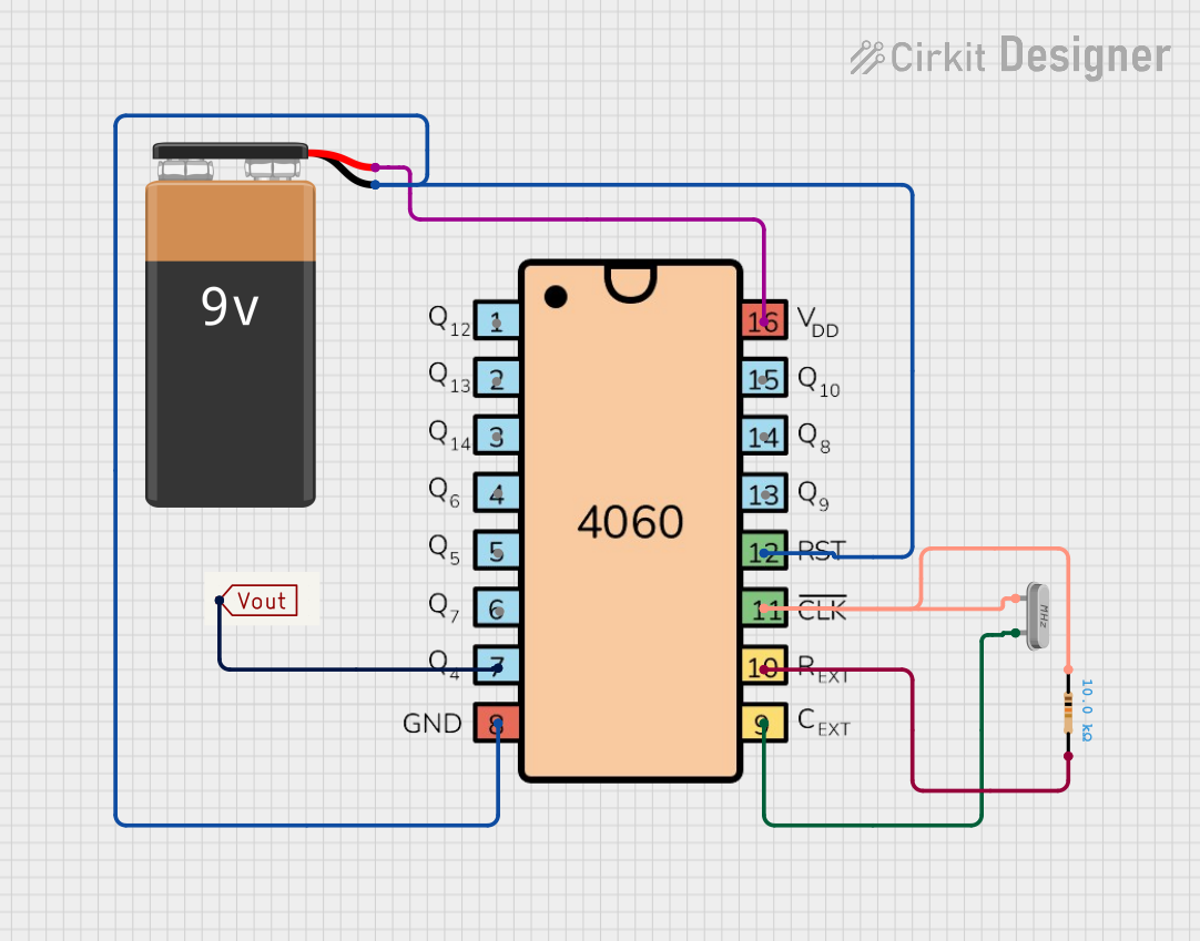 Open Project in Cirkit Designer
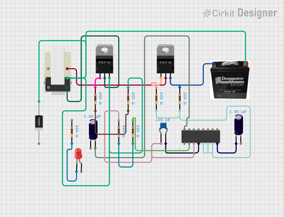 Open Project in Cirkit Designer
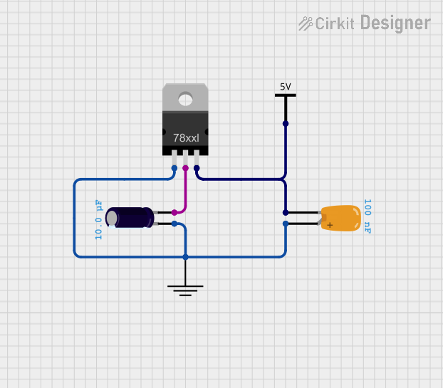 Open Project in Cirkit Designer
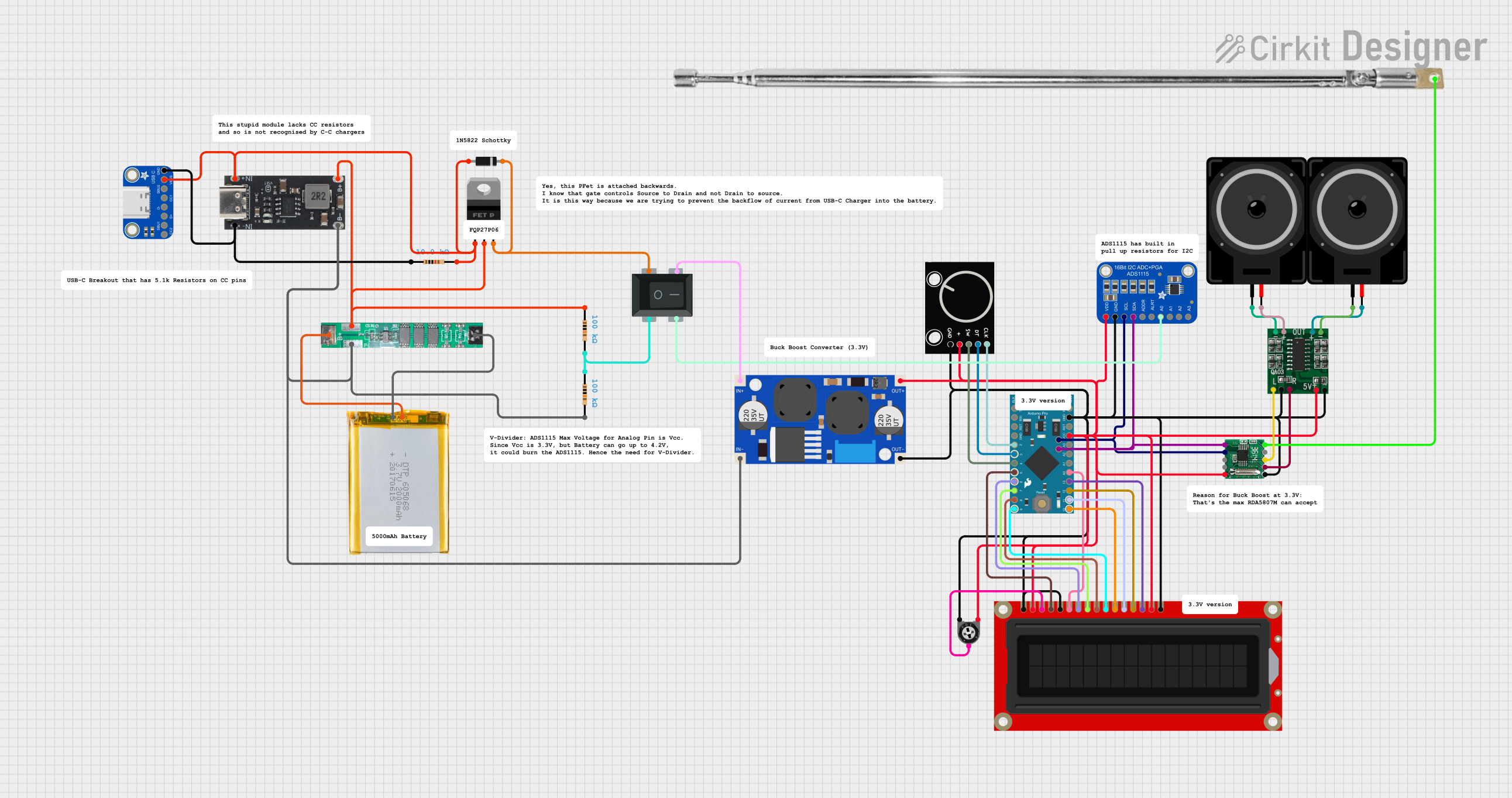 Open Project in Cirkit Designer
Explore Projects Built with AD654 - Low Cost Monolithic Voltage-to-Frequency Converter
Open Project in Cirkit DesignerOpen Project in Cirkit DesignerOpen Project in Cirkit DesignerOpen Project in Cirkit DesignerCommon Applications and Use Cases
- Analog-to-digital conversion (ADC) systems
- Frequency modulation and demodulation
- Data transmission in noisy environments
- Signal isolation and long-distance transmission
- Industrial process control and instrumentation
- Pulse-width modulation (PWM) systems
Technical Specifications
The following table outlines the key technical specifications of the AD654:
| Parameter | Value |
|---|---|
| Supply Voltage Range | +4.5 V to +36 V |
| Input Voltage Range | 0 V to 10 V |
| Output Frequency Range | 1 Hz to 500 kHz |
| Linearity Error | ±0.03% (typical) |
| Temperature Range | 0°C to +70°C (commercial grade) |
| Supply Current | 1.2 mA (typical) |
| Output Drive Capability | TTL/CMOS compatible |
| Package Type | 8-pin PDIP (AD654JNZ) |
Pin Configuration and Descriptions
The AD654 is an 8-pin device. The pinout and descriptions are as follows:
| Pin Number | Pin Name | Description |
|---|---|---|
| 1 | VIN | Analog input voltage (0 V to 10 V). This is the signal to be converted to frequency. |
| 2 | GND | Ground reference for the device. |
| 3 | RSET | External resistor to set the full-scale frequency. |
| 4 | CSET | External capacitor to set the frequency range. |
| 5 | V+ | Positive supply voltage (+4.5 V to +36 V). |
| 6 | FOUT | Frequency output signal (TTL/CMOS compatible). |
| 7 | NC | No connection. Leave this pin unconnected. |
| 8 | VREF | Internal reference voltage output (nominally 1.2 V). |
Usage Instructions
How to Use the AD654 in a Circuit
- Power Supply: Connect the V+ pin to a DC power supply within the range of +4.5 V to +36 V. Connect the GND pin to the ground of the circuit.
- Input Voltage: Apply the analog input voltage (0 V to 10 V) to the VIN pin. Ensure the input voltage does not exceed the specified range to avoid damage.
- Frequency Setting:
- Connect an external resistor to the RSET pin to set the full-scale frequency. The recommended value is typically in the range of 10 kΩ to 1 MΩ.
- Connect an external capacitor to the CSET pin to set the frequency range. Typical values are in the range of 100 pF to 10 nF.
- Output Signal: The frequency output is available at the FOUT pin. This signal is TTL/CMOS compatible and can be directly interfaced with digital systems.
- Reference Voltage: The VREF pin provides a stable 1.2 V reference voltage, which can be used for calibration or as a reference for other components in the circuit.
Important Considerations and Best Practices
- Use precision resistors and capacitors for RSET and CSET to ensure high accuracy and stability.
- Keep the input voltage free from noise to avoid frequency jitter in the output.
- Decouple the power supply with a 0.1 µF ceramic capacitor close to the V+ pin to minimize power supply noise.
- Avoid leaving unused pins floating. For example, ensure the NC pin is left unconnected as specified.
Example: Interfacing AD654 with Arduino UNO
The AD654 can be used with an Arduino UNO to measure an analog voltage and convert it to a frequency signal. Below is an example code snippet:
// Example: Reading frequency output from AD654 using Arduino UNO
// Connect AD654 FOUT pin to Arduino digital pin 2 (interrupt pin)

const int freqPin = 2; // Pin connected to AD654 FOUT
volatile unsigned long pulseCount = 0; // Variable to store pulse count

void setup() {
  pinMode(freqPin, INPUT); // Set freqPin as input
  attachInterrupt(digitalPinToInterrupt(freqPin), countPulses, RISING);
  Serial.begin(9600); // Initialize serial communication
}

void loop() {
  delay(1000); // Wait for 1 second
  noInterrupts(); // Disable interrupts to read pulseCount safely
  unsigned long frequency = pulseCount; // Frequency in Hz
  pulseCount = 0; // Reset pulse count
  interrupts(); // Re-enable interrupts
  Serial.print("Frequency: ");
  Serial.print(frequency);
  Serial.println(" Hz");
}

void countPulses() {
  pulseCount++; // Increment pulse count on each rising edge
}
Notes:
- Ensure the FOUT pin is connected to a digital input pin on the Arduino that supports interrupts.
- The code calculates the frequency by counting pulses over a 1-second interval.
Troubleshooting and FAQs
Common Issues and Solutions
No Output Signal:
- Verify the power supply connections to the V+ and GND pins.
- Check the external resistor and capacitor values connected to RSET and CSET.
- Ensure the input voltage at VIN is within the specified range.
Inaccurate Frequency Output:
- Use precision components for RSET and CSET to minimize errors.
- Ensure the input voltage is stable and free from noise.
- Verify the calibration of the circuit using the VREF pin.
High Frequency Jitter:
- Add a decoupling capacitor (e.g., 0.1 µF) close to the V+ pin to reduce power supply noise.
- Shield the input signal to prevent external interference.
FAQs
Q: Can the AD654 operate with a single supply voltage?
A: Yes, the AD654 is designed to operate with a single supply voltage ranging from +4.5 V to +36 V.
Q: What is the maximum output frequency of the AD654?
A: The maximum output frequency is 500 kHz, depending on the values of RSET and CSET.
Q: Is the output signal compatible with microcontrollers?
A: Yes, the output signal at the FOUT pin is TTL/CMOS compatible and can be directly interfaced with microcontrollers like Arduino.
Q: Can I use the AD654 for bidirectional voltage-to-frequency conversion?
A: No, the AD654 is designed for unidirectional voltage-to-frequency conversion only.