Cirkit Designer Logo
Cirkit Designer
Your all-in-one circuit design IDE
Home / 
Component Documentation

How to Use 16304-SparkFun_Qwiic_TMP102_Digital_Temp_Sensor: Examples, Pinouts, and Specs

Image of 16304-SparkFun_Qwiic_TMP102_Digital_Temp_Sensor
Cirkit Designer LogoDesign with 16304-SparkFun_Qwiic_TMP102_Digital_Temp_Sensor in Cirkit Designer

Introduction

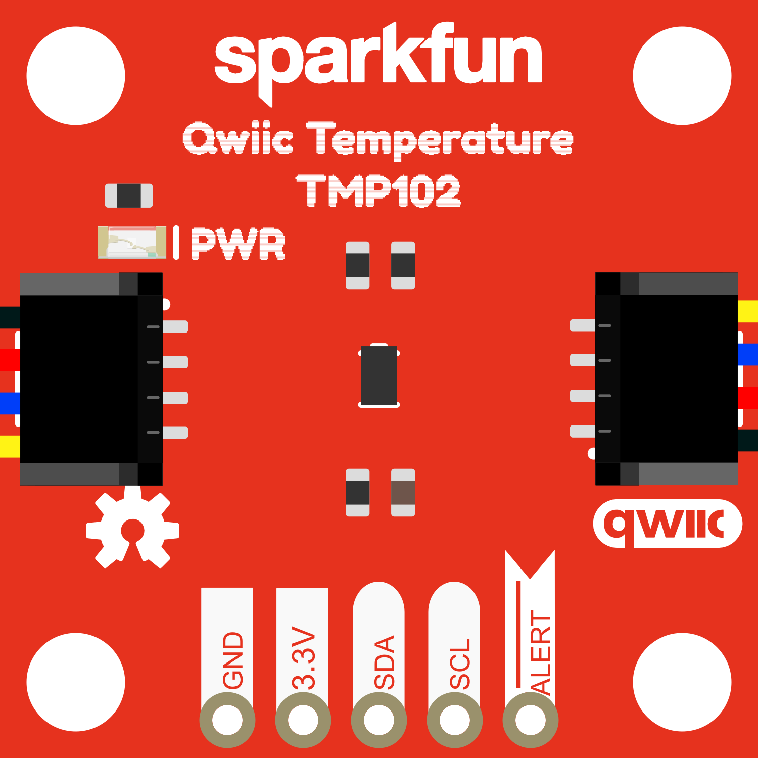
The 16304-SparkFun Qwiic TMP102 Digital Temp Sensor is a high-precision digital temperature sensor designed for easy integration into projects and products. Utilizing the TMP102 sensor chip, this breakout board is ideal for environmental temperature sensing for home automation, industrial systems, and weather stations. Its Qwiic connector system enables quick, solderless connection to other Qwiic-compatible devices, making it a convenient choice for rapid prototyping and educational purposes.

Explore Projects Built with 16304-SparkFun_Qwiic_TMP102_Digital_Temp_Sensor

Use Cirkit Designer to design, explore, and prototype these projects online. Some projects support real-time simulation. Click "Open Project" to start designing instantly!
Battery-Powered Health Monitoring System with Nucleo WB55RG and OLED Display
Image of Pulsefex: A project utilizing 16304-SparkFun_Qwiic_TMP102_Digital_Temp_Sensor in a practical application
This circuit is a multi-sensor data acquisition system that uses a Nucleo WB55RG microcontroller to interface with a digital temperature sensor (TMP102), a pulse oximeter and heart-rate sensor (MAX30102), and a 0.96" OLED display via I2C. Additionally, it includes a Sim800l module for GSM communication, powered by a 3.7V LiPo battery.
Cirkit Designer LogoOpen Project in Cirkit Designer
ESP8266 NodeMCU with DS18B20 Temperature Sensor Monitoring
Image of SUHU: A project utilizing 16304-SparkFun_Qwiic_TMP102_Digital_Temp_Sensor in a practical application
This circuit features an ESP8266 NodeMCU microcontroller connected to a DS18B20 temperature sensor. The sensor's data line (DQ) is connected to the D2 pin of the NodeMCU through a 4.7k ohm pull-up resistor, which is a common configuration for one-wire temperature sensors. The sensor is powered by the 3.3V supply from the NodeMCU, and both the sensor and the NodeMCU share a common ground.
Cirkit Designer LogoOpen Project in Cirkit Designer
ESP32-Based Infrared Thermometer with I2C LCD Display
Image of infrared thermometer 2: A project utilizing 16304-SparkFun_Qwiic_TMP102_Digital_Temp_Sensor in a practical application
This circuit features an ESP32 microcontroller interfaced with an MLX90614 infrared temperature sensor and a 16x2 I2C LCD display for temperature readouts. A tactile button is connected to the ESP32 to trigger temperature measurements, and an LED indicates when a measurement is in progress. The circuit is powered by an 18650 Li-Ion battery, with appropriate resistors for LED current limiting and button debouncing.
Cirkit Designer LogoOpen Project in Cirkit Designer
ESP32-Based Battery-Powered Wi-Fi Temperature Monitoring System with MLX90614 and I2C LCD
Image of infrared thermometer 4: A project utilizing 16304-SparkFun_Qwiic_TMP102_Digital_Temp_Sensor in a practical application
This circuit is a temperature monitoring system using an ESP32 microcontroller, an MLX90614 infrared temperature sensor, and a 16x2 I2C LCD display. It includes a TP4056 module for charging a 18650 Li-Ion battery, a pushbutton for mode selection, and a buzzer for low battery alerts. The ESP32 reads temperature data, displays it on the LCD, and sends it to a server via Wi-Fi.
Cirkit Designer LogoOpen Project in Cirkit Designer

Explore Projects Built with 16304-SparkFun_Qwiic_TMP102_Digital_Temp_Sensor

Use Cirkit Designer to design, explore, and prototype these projects online. Some projects support real-time simulation. Click "Open Project" to start designing instantly!
Image of Pulsefex: A project utilizing 16304-SparkFun_Qwiic_TMP102_Digital_Temp_Sensor in a practical application
Battery-Powered Health Monitoring System with Nucleo WB55RG and OLED Display
This circuit is a multi-sensor data acquisition system that uses a Nucleo WB55RG microcontroller to interface with a digital temperature sensor (TMP102), a pulse oximeter and heart-rate sensor (MAX30102), and a 0.96" OLED display via I2C. Additionally, it includes a Sim800l module for GSM communication, powered by a 3.7V LiPo battery.
Cirkit Designer LogoOpen Project in Cirkit Designer
Image of SUHU: A project utilizing 16304-SparkFun_Qwiic_TMP102_Digital_Temp_Sensor in a practical application
ESP8266 NodeMCU with DS18B20 Temperature Sensor Monitoring
This circuit features an ESP8266 NodeMCU microcontroller connected to a DS18B20 temperature sensor. The sensor's data line (DQ) is connected to the D2 pin of the NodeMCU through a 4.7k ohm pull-up resistor, which is a common configuration for one-wire temperature sensors. The sensor is powered by the 3.3V supply from the NodeMCU, and both the sensor and the NodeMCU share a common ground.
Cirkit Designer LogoOpen Project in Cirkit Designer
Image of infrared thermometer 2: A project utilizing 16304-SparkFun_Qwiic_TMP102_Digital_Temp_Sensor in a practical application
ESP32-Based Infrared Thermometer with I2C LCD Display
This circuit features an ESP32 microcontroller interfaced with an MLX90614 infrared temperature sensor and a 16x2 I2C LCD display for temperature readouts. A tactile button is connected to the ESP32 to trigger temperature measurements, and an LED indicates when a measurement is in progress. The circuit is powered by an 18650 Li-Ion battery, with appropriate resistors for LED current limiting and button debouncing.
Cirkit Designer LogoOpen Project in Cirkit Designer
Image of infrared thermometer 4: A project utilizing 16304-SparkFun_Qwiic_TMP102_Digital_Temp_Sensor in a practical application
ESP32-Based Battery-Powered Wi-Fi Temperature Monitoring System with MLX90614 and I2C LCD
This circuit is a temperature monitoring system using an ESP32 microcontroller, an MLX90614 infrared temperature sensor, and a 16x2 I2C LCD display. It includes a TP4056 module for charging a 18650 Li-Ion battery, a pushbutton for mode selection, and a buzzer for low battery alerts. The ESP32 reads temperature data, displays it on the LCD, and sends it to a server via Wi-Fi.
Cirkit Designer LogoOpen Project in Cirkit Designer

Common Applications and Use Cases

  • Environmental monitoring
  • Data logging
  • HVAC systems
  • Consumer electronics
  • Wearable devices

Technical Specifications

Key Technical Details

  • Temperature Range: -40°C to +125°C
  • Accuracy: ±0.5°C (from -25°C to +85°C)
  • Resolution: 0.0625°C
  • Supply Voltage: 1.4V to 3.6V
  • Interface: I2C
  • I2C Address: 0x48 (default), 0x49, 0x4A, 0x4B (with jumpers)

Pin Configuration and Descriptions

Pin Number Name Description
1 GND Ground connection
2 VCC Power supply (1.4V to 3.6V)
3 SDA I2C Data line
4 SCL I2C Clock line
5 ADD0 Address select pin
6 ALRT Alert pin

Usage Instructions

How to Use the Component in a Circuit

  1. Powering the Sensor: Connect the VCC pin to a power supply within the range of 1.4V to 3.6V and the GND pin to the ground of your system.
  2. I2C Communication: Connect the SDA and SCL pins to your microcontroller's I2C data and clock lines, respectively.
  3. Address Selection: If multiple TMP102 sensors are used on the same I2C bus, configure the ADD0 pin to set different addresses.
  4. Alert Functionality: The ALRT pin can be used as an interrupt or comparator output for temperature threshold events.

Important Considerations and Best Practices

  • Ensure that the power supply is within the specified voltage range to prevent damage.
  • Use pull-up resistors on the I2C lines if they are not already present on your microcontroller board.
  • Avoid placing the sensor near heat-generating components to ensure accurate readings.
  • For optimal performance, calibrate the sensor in the final application environment.

Example Code for Arduino UNO

#include <Wire.h>

// TMP102 I2C address is 0x48 (default)
#define Addr 0x48

void setup() {
  // Initialise I2C communication as MASTER
  Wire.begin();
  // Initialise serial communication, set baud rate = 9600
  Serial.begin(9600);
  
  // Start I2C Transmission
  Wire.beginTransmission(Addr);
  // Select configuration register
  Wire.write(0x01);
  // Set continuous conversion mode, 12-bit resolution
  Wire.write(0x60);
  // Stop I2C Transmission
  Wire.endTransmission();
  delay(300);
}

void loop() {
  unsigned int data[2];

  // Start I2C Transmission
  Wire.beginTransmission(Addr);
  // Select data register
  Wire.write(0x00);
  // Stop I2C Transmission
  Wire.endTransmission();

  // Request 2 bytes of data
  Wire.requestFrom(Addr, 2);

  // Read 2 bytes of data
  // temp msb, temp lsb
  if (Wire.available() == 2) {
    data[0] = Wire.read();
    data[1] = Wire.read();
  }

  // Convert the data to 12-bits
  int temp = ((data[0] * 256) + (data[1] & 0xF0)) / 16;
  if (temp > 2047) {
    temp -= 4096;
  }
  float celsius = temp * 0.0625;
  float fahrenheit = (celsius * 1.8) + 32;

  // Output data to serial monitor
  Serial.print("Temperature in Celsius: ");
  Serial.print(celsius);
  Serial.println(" C");
  Serial.print("Temperature in Fahrenheit: ");
  Serial.print(fahrenheit);
  Serial.println(" F");

  delay(500);
}

Troubleshooting and FAQs

Common Issues Users Might Face

  • Inaccurate Temperature Readings: Ensure the sensor is not placed near heat sources and that it has been properly calibrated.
  • No Data on I2C: Check connections and ensure pull-up resistors are in place. Verify that the correct I2C address is being used.

Solutions and Tips for Troubleshooting

  • Sensor Not Responding: Double-check wiring, especially the VCC and GND connections. Ensure that the microcontroller's power supply is stable.
  • Multiple Sensors on I2C: Use different addresses for each sensor by configuring the ADD0 pin and ensure no address conflict occurs.

FAQs

Q: Can the sensor be used with a 5V system? A: While the sensor operates at 1.4V to 3.6V, level shifters can be used for interfacing with a 5V system.

Q: How can I change the I2C address of the sensor? A: The I2C address can be changed by connecting the ADD0 pin to GND, VCC, SDA, or SCL, corresponding to addresses 0x48, 0x49, 0x4A, or 0x4B, respectively.

Q: What is the maximum distance for the I2C bus? A: I2C is typically used for short distances, but with proper bus buffering and termination, longer distances can be achieved. Keep the lines as short as possible for reliable communication.