Cirkit Designer Logo
Cirkit Designer
Your all-in-one circuit design IDE
Home / 
Component Documentation

How to Use ESP32 (30 pin): Examples, Pinouts, and Specs

Image of ESP32 (30 pin)
Cirkit Designer LogoDesign with ESP32 (30 pin) in Cirkit Designer

Introduction

The ESP32, manufactured by Espressif, is a powerful and versatile microcontroller designed for IoT (Internet of Things) applications and embedded systems. It features built-in Wi-Fi and Bluetooth capabilities, making it an excellent choice for wireless communication projects. With its 30-pin configuration, the ESP32 provides a wide range of GPIO (General Purpose Input/Output) pins, ADC (Analog-to-Digital Converter) channels, and other peripherals, enabling developers to create complex and efficient systems.

Explore Projects Built with ESP32 (30 pin)

Use Cirkit Designer to design, explore, and prototype these projects online. Some projects support real-time simulation. Click "Open Project" to start designing instantly!
ESP32-Based Smart Display with Camera and Audio Alert System
Image of cam_circuit_design: A project utilizing ESP32 (30 pin) in a practical application
This circuit features two ESP32 microcontrollers, one standard 30-pin version and one ESP32-CAM module, both sharing a common ground and power supply. The 30-pin ESP32 is interfaced with an I2C LCD 16x2 Screen for display purposes, using its I2C pins (D21 for SDA and D22 for SCL), and controls a buzzer connected to pin D23. Additionally, the ESP32-CAM is connected to the 30-pin ESP32 via serial communication through pins TX2 and RX2 for potential image data transfer.
Cirkit Designer LogoOpen Project in Cirkit Designer
ESP32-Based Environmental Monitoring System with Water Flow Sensing
Image of Water: A project utilizing ESP32 (30 pin) in a practical application
This circuit features an ESP32 Devkit V1 microcontroller connected to a DHT22 temperature and humidity sensor and a water flow sensor. The ESP32 reads environmental data from the DHT22 via a digital input pin (D33) and monitors water flow through the water flow sensor connected to another digital input pin (D23). The ESP32 is powered through its VIN pin, and both sensors are powered by the ESP32's 3V3 output, with common ground connections.
Cirkit Designer LogoOpen Project in Cirkit Designer
ESP32-Based OLED Display Interface
Image of d: A project utilizing ESP32 (30 pin) in a practical application
This circuit features an ESP32 microcontroller connected to an OLED 1.3" display. The ESP32's GPIO pins 21 and 22 are used for I2C communication (SDA and SCL respectively) with the OLED display. The display is powered by the 5V output from the ESP32, and both devices share a common ground.
Cirkit Designer LogoOpen Project in Cirkit Designer
ESP32-Based Environmental Monitoring System with OLED Display
Image of esproj: A project utilizing ESP32 (30 pin) in a practical application
This circuit features an ESP32 microcontroller as the central processing unit, interfacing with a DHT11 temperature and humidity sensor, an MPU-6050 accelerometer and gyroscope, an OLED display, and a separate temperature sensor. The ESP32 communicates with the MPU-6050 and the OLED display via I2C (using pins D22 and D21 for SCL and SDA, respectively), reads temperature data from the DHT11 sensor through pin D18, and interfaces with the additional temperature sensor via pin D5. All components share a common power supply connected to the ESP32's Vin pin and a common ground.
Cirkit Designer LogoOpen Project in Cirkit Designer

Explore Projects Built with ESP32 (30 pin)

Use Cirkit Designer to design, explore, and prototype these projects online. Some projects support real-time simulation. Click "Open Project" to start designing instantly!
Image of cam_circuit_design: A project utilizing ESP32 (30 pin) in a practical application
ESP32-Based Smart Display with Camera and Audio Alert System
This circuit features two ESP32 microcontrollers, one standard 30-pin version and one ESP32-CAM module, both sharing a common ground and power supply. The 30-pin ESP32 is interfaced with an I2C LCD 16x2 Screen for display purposes, using its I2C pins (D21 for SDA and D22 for SCL), and controls a buzzer connected to pin D23. Additionally, the ESP32-CAM is connected to the 30-pin ESP32 via serial communication through pins TX2 and RX2 for potential image data transfer.
Cirkit Designer LogoOpen Project in Cirkit Designer
Image of Water: A project utilizing ESP32 (30 pin) in a practical application
ESP32-Based Environmental Monitoring System with Water Flow Sensing
This circuit features an ESP32 Devkit V1 microcontroller connected to a DHT22 temperature and humidity sensor and a water flow sensor. The ESP32 reads environmental data from the DHT22 via a digital input pin (D33) and monitors water flow through the water flow sensor connected to another digital input pin (D23). The ESP32 is powered through its VIN pin, and both sensors are powered by the ESP32's 3V3 output, with common ground connections.
Cirkit Designer LogoOpen Project in Cirkit Designer
Image of d: A project utilizing ESP32 (30 pin) in a practical application
ESP32-Based OLED Display Interface
This circuit features an ESP32 microcontroller connected to an OLED 1.3" display. The ESP32's GPIO pins 21 and 22 are used for I2C communication (SDA and SCL respectively) with the OLED display. The display is powered by the 5V output from the ESP32, and both devices share a common ground.
Cirkit Designer LogoOpen Project in Cirkit Designer
Image of esproj: A project utilizing ESP32 (30 pin) in a practical application
ESP32-Based Environmental Monitoring System with OLED Display
This circuit features an ESP32 microcontroller as the central processing unit, interfacing with a DHT11 temperature and humidity sensor, an MPU-6050 accelerometer and gyroscope, an OLED display, and a separate temperature sensor. The ESP32 communicates with the MPU-6050 and the OLED display via I2C (using pins D22 and D21 for SCL and SDA, respectively), reads temperature data from the DHT11 sensor through pin D18, and interfaces with the additional temperature sensor via pin D5. All components share a common power supply connected to the ESP32's Vin pin and a common ground.
Cirkit Designer LogoOpen Project in Cirkit Designer

Common Applications and Use Cases

  • IoT devices and smart home automation
  • Wireless sensor networks
  • Wearable technology
  • Robotics and automation systems
  • Data logging and remote monitoring
  • Bluetooth-enabled devices and applications

Technical Specifications

The ESP32 (30-pin variant) is packed with features that make it suitable for a wide range of applications. Below are its key technical specifications:

Key Technical Details

  • Microcontroller: Dual-core Xtensa® 32-bit LX6
  • Clock Speed: Up to 240 MHz
  • Flash Memory: 4 MB (varies by module)
  • SRAM: 520 KB
  • Wi-Fi: 802.11 b/g/n (2.4 GHz)
  • Bluetooth: v4.2 BR/EDR and BLE
  • Operating Voltage: 3.3V
  • Input Voltage Range: 5V (via USB) or 7-12V (via VIN pin)
  • GPIO Pins: 30 (multipurpose)
  • ADC Channels: 18 (12-bit resolution)
  • DAC Channels: 2
  • PWM Outputs: 16
  • I2C Interfaces: 2
  • SPI Interfaces: 4
  • UART Interfaces: 3
  • Operating Temperature: -40°C to 125°C

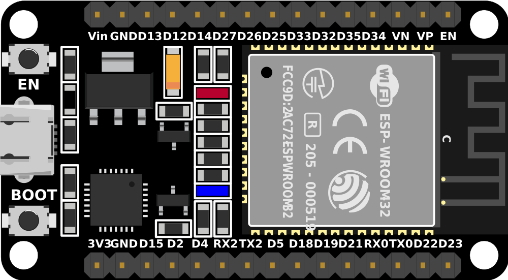
Pin Configuration and Descriptions

The ESP32 (30-pin variant) has the following pinout:

Pin Name Type Description
VIN Power Input Input voltage (7-12V) for powering the ESP32.
3V3 Power Output 3.3V regulated output.
GND Ground Ground connection.
EN Input Enable pin. Pull high to enable the chip.
IO0 GPIO/Boot Mode GPIO0. Used to enter bootloader mode when pulled low during reset.
IO1-IO39 GPIO General-purpose input/output pins. Some pins have special functions (see below).
ADC1/ADC2 Analog Input Analog-to-digital converter channels.
DAC1/DAC2 Analog Output Digital-to-analog converter channels.
TX0/RX0 UART UART0 TX and RX pins for serial communication.
SCL/SDA I2C I2C clock (SCL) and data (SDA) pins.
MOSI/MISO/SCK SPI SPI data and clock pins.

Note: Some GPIO pins are input-only or have specific restrictions. Refer to the Espressif datasheet for detailed pin capabilities.

Usage Instructions

The ESP32 is easy to integrate into a variety of projects. Below are the steps and best practices for using the ESP32 in a circuit.

How to Use the ESP32 in a Circuit

  1. Powering the ESP32:

    • Use the VIN pin to supply 7-12V, or connect a 5V USB power source.
    • Ensure the 3.3V pin is not overloaded, as it is a regulated output.
  2. Connecting Peripherals:

    • Use GPIO pins for digital input/output.
    • Connect sensors to ADC pins for analog input.
    • Use I2C, SPI, or UART interfaces for communication with other devices.
  3. Programming the ESP32:

    • Install the Arduino IDE or Espressif's ESP-IDF development environment.
    • Add the ESP32 board package to the Arduino IDE via the Board Manager.
    • Connect the ESP32 to your computer using a USB cable.
    • Select the correct board and port in the IDE, then upload your code.

Example Code for Arduino IDE

The following example demonstrates how to blink an LED connected to GPIO2:

// Define the GPIO pin for the LED
#define LED_PIN 2

void setup() {
  // Set the LED pin as an output
  pinMode(LED_PIN, OUTPUT);
}

void loop() {
  // Turn the LED on
  digitalWrite(LED_PIN, HIGH);
  delay(1000); // Wait for 1 second

  // Turn the LED off
  digitalWrite(LED_PIN, LOW);
  delay(1000); // Wait for 1 second
}

Important Considerations and Best Practices

  • Avoid using GPIO6-GPIO11 for general I/O, as these are connected to the internal flash memory.
  • Use level shifters if interfacing with 5V logic devices, as the ESP32 operates at 3.3V.
  • Ensure proper grounding to avoid noise and instability in analog readings.
  • Use decoupling capacitors near power pins to stabilize the power supply.

Troubleshooting and FAQs

Common Issues and Solutions

  1. ESP32 Not Detected by Computer:

    • Ensure the USB cable is functional and supports data transfer.
    • Install the correct USB-to-serial driver for your operating system.
  2. Code Upload Fails:

    • Check that the correct board and port are selected in the Arduino IDE.
    • Hold the BOOT button while uploading to enter bootloader mode.
  3. Wi-Fi Connection Issues:

    • Verify the SSID and password in your code.
    • Ensure the router is within range and supports 2.4 GHz Wi-Fi.
  4. Random Resets or Instability:

    • Check the power supply for sufficient current (at least 500mA).
    • Avoid using GPIO pins connected to internal flash memory.

FAQs

Q: Can the ESP32 operate on battery power?
A: Yes, the ESP32 can be powered by a LiPo battery connected to the VIN pin. Use a voltage regulator if necessary.

Q: How do I use the ESP32's Bluetooth functionality?
A: The ESP32 supports both Bluetooth Classic and BLE. Use the BluetoothSerial or BLE libraries in the Arduino IDE to implement Bluetooth features.

Q: Can I use the ESP32 with 5V sensors?
A: Yes, but you must use a level shifter to convert the 5V signals to 3.3V to avoid damaging the ESP32.

Q: What is the maximum number of devices the ESP32 can connect to via Wi-Fi?
A: The ESP32 can act as a Wi-Fi access point and support up to 10 devices simultaneously.

By following this documentation, you can effectively use the ESP32 (30-pin variant) in your projects and troubleshoot common issues with ease.