How to Use DC-DC Converter: Examples, Pinouts, and Specs
Introduction
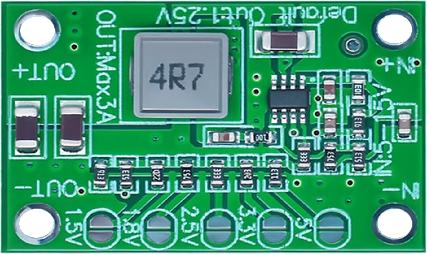
The Hailege MP1495 is a high-efficiency DC-DC converter designed to step down or regulate a higher DC voltage to a lower, stable DC voltage. This component is widely used in power management systems, enabling efficient energy transfer and voltage regulation in electronic devices. Its compact design and robust performance make it ideal for applications such as battery-powered devices, industrial automation, and embedded systems.
Explore Projects Built with DC-DC Converter


Explore Projects Built with DC-DC Converter
Common Applications and Use Cases
- Powering microcontrollers and sensors in embedded systems
- Voltage regulation in battery-powered devices
- Industrial automation and control systems
- LED drivers and lighting systems
- Consumer electronics, such as portable chargers and adapters
Technical Specifications
The Hailege MP1495 DC-DC converter is a step-down (buck) converter with the following key specifications:
| Parameter | Value |
|---|---|
| Input Voltage Range | 4.5V to 36V |
| Output Voltage Range | 0.8V to 30V |
| Maximum Output Current | 3A |
| Efficiency | Up to 95% |
| Switching Frequency | 500kHz |
| Operating Temperature | -40°C to +85°C |
| Package Type | SOP-8 |
Pin Configuration and Descriptions
The MP1495 features an 8-pin configuration. Below is the pinout and description:
| Pin Number | Pin Name | Description |
|---|---|---|
| 1 | VIN | Input voltage pin. Connect to the DC input source (4.5V to 36V). |
| 2 | SW | Switching node. Connect to the inductor and diode. |
| 3 | GND | Ground pin. Connect to the system ground. |
| 4 | FB | Feedback pin. Connect to a resistor divider to set the output voltage. |
| 5 | EN | Enable pin. Drive high to enable the converter, or low to disable it. |
| 6 | COMP | Compensation pin. Connect a capacitor to stabilize the control loop. |
| 7 | BST | Bootstrap pin. Connect a capacitor between BST and SW for high-side driving. |
| 8 | NC | No connection. Leave this pin unconnected. |
Usage Instructions
How to Use the MP1495 in a Circuit
- Input Voltage Connection: Connect the input voltage source (4.5V to 36V) to the VIN pin. Ensure the input voltage is within the specified range.
- Output Voltage Setting: Use a resistor divider network connected to the FB pin to set the desired output voltage. The formula for output voltage is: [ V_{OUT} = 0.8 \times \left(1 + \frac{R1}{R2}\right) ] where ( R1 ) and ( R2 ) are the resistors in the divider.
- Inductor and Capacitor Selection: Choose an appropriate inductor and output capacitor based on the desired output voltage and current. Refer to the datasheet for recommended values.
- Enable Pin: Drive the EN pin high (logic level 1) to enable the converter. Pull it low (logic level 0) to disable it.
- Bootstrap Capacitor: Connect a 0.1µF capacitor between the BST and SW pins for proper operation of the high-side MOSFET.
Important Considerations and Best Practices
- Use low-ESR capacitors for input and output filtering to minimize noise and improve stability.
- Ensure proper thermal management by providing adequate PCB copper area for heat dissipation.
- Place the feedback resistor divider as close as possible to the FB pin to reduce noise interference.
- Avoid exceeding the maximum input voltage (36V) or output current (3A) to prevent damage to the component.
Example: Connecting the MP1495 to an Arduino UNO
The MP1495 can be used to power an Arduino UNO by stepping down a 12V input to 5V. Below is an example circuit and Arduino code:
Circuit Connections
- Connect a 12V DC source to the VIN pin of the MP1495.
- Set the output voltage to 5V using a resistor divider (e.g., ( R1 = 10k\Omega ), ( R2 = 2k\Omega )).
- Connect the output of the MP1495 to the 5V pin of the Arduino UNO.
- Connect the GND pin of the MP1495 to the Arduino GND.
Arduino Code Example
// Example code to blink an LED using Arduino UNO powered by MP1495 DC-DC converter

const int ledPin = 13; // Pin connected to the onboard LED

void setup() {
  pinMode(ledPin, OUTPUT); // Set the LED pin as an output
}

void loop() {
  digitalWrite(ledPin, HIGH); // Turn the LED on
  delay(1000);                // Wait for 1 second
  digitalWrite(ledPin, LOW);  // Turn the LED off
  delay(1000);                // Wait for 1 second
}
Troubleshooting and FAQs
Common Issues and Solutions
No Output Voltage
- Cause: The EN pin is not driven high.
- Solution: Ensure the EN pin is connected to a logic high signal or VIN through a pull-up resistor.
Output Voltage is Unstable
- Cause: Incorrect compensation network or insufficient output capacitance.
- Solution: Verify the compensation capacitor value on the COMP pin and use low-ESR output capacitors.
Excessive Heat
- Cause: Overloading or insufficient heat dissipation.
- Solution: Reduce the load current or improve PCB thermal design with larger copper areas.
High Noise on Output
- Cause: Poor layout or inadequate filtering.
- Solution: Use proper grounding techniques and add additional filtering capacitors.
FAQs
Q: Can the MP1495 be used for step-up (boost) applications?
A: No, the MP1495 is a step-down (buck) converter and cannot be used for step-up applications.
Q: What is the maximum efficiency of the MP1495?
A: The MP1495 can achieve up to 95% efficiency under optimal conditions.
Q: Can I use the MP1495 with a 24V input to power a 3.3V device?
A: Yes, the MP1495 supports a wide input voltage range (4.5V to 36V) and can step down to 3.3V with proper resistor selection.
Q: Is the MP1495 suitable for battery-powered applications?
A: Yes, its high efficiency and low quiescent current make it ideal for battery-powered devices.