How to Use watt meter: Examples, Pinouts, and Specs
Introduction
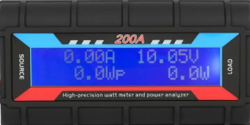
A watt meter is an instrument used to measure the electrical power in watts of any given circuit. It is capable of measuring both AC and DC power, making it a versatile tool for a wide range of applications. This component is essential for monitoring energy consumption, evaluating system efficiency, and diagnosing power-related issues in electrical circuits.
Explore Projects Built with watt meter
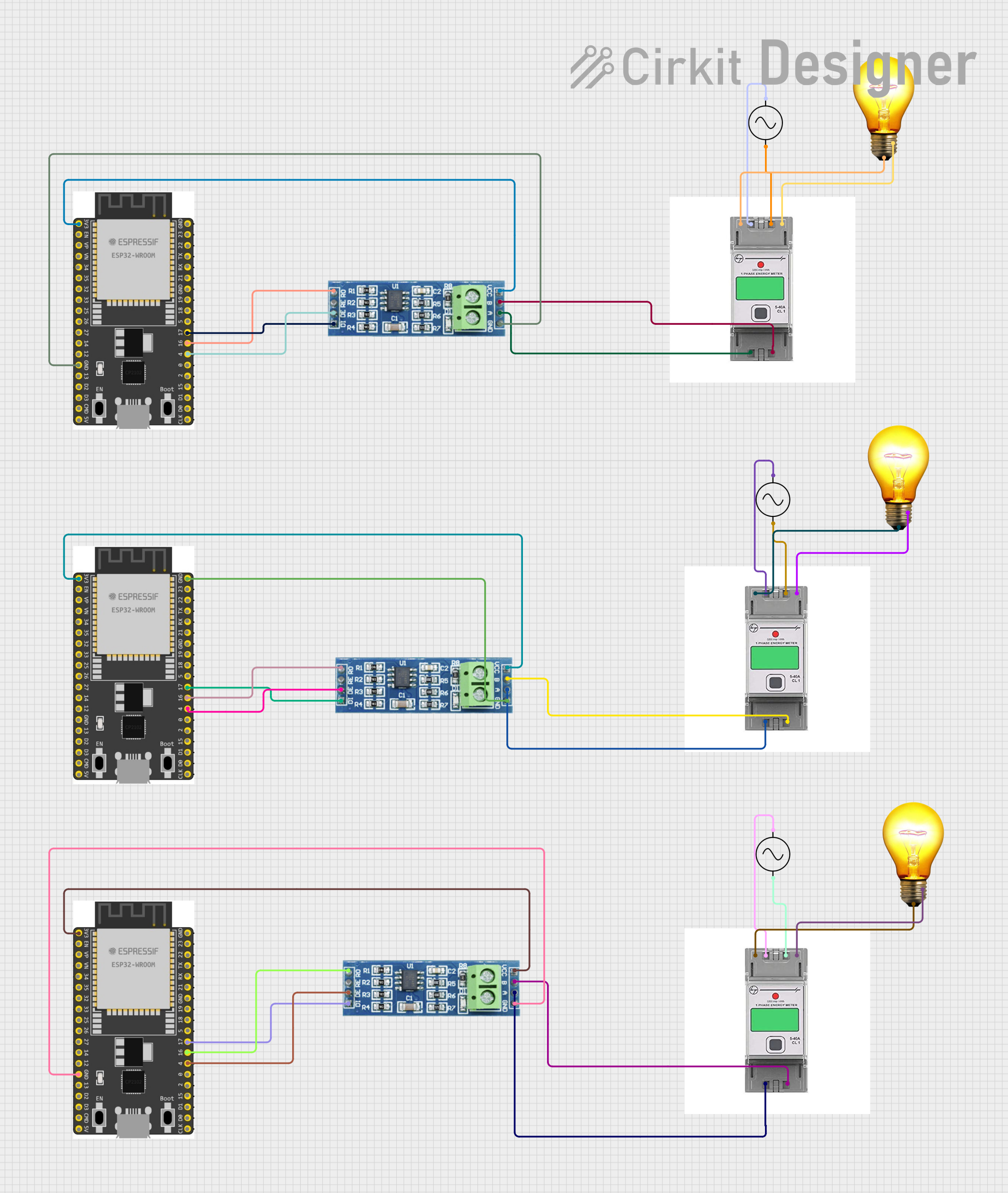
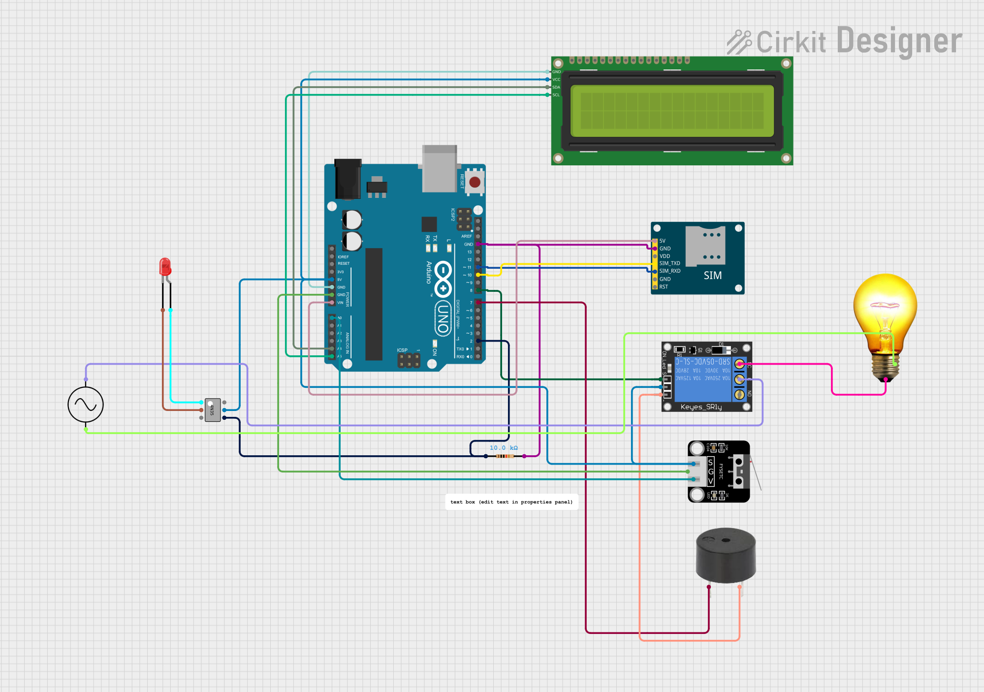
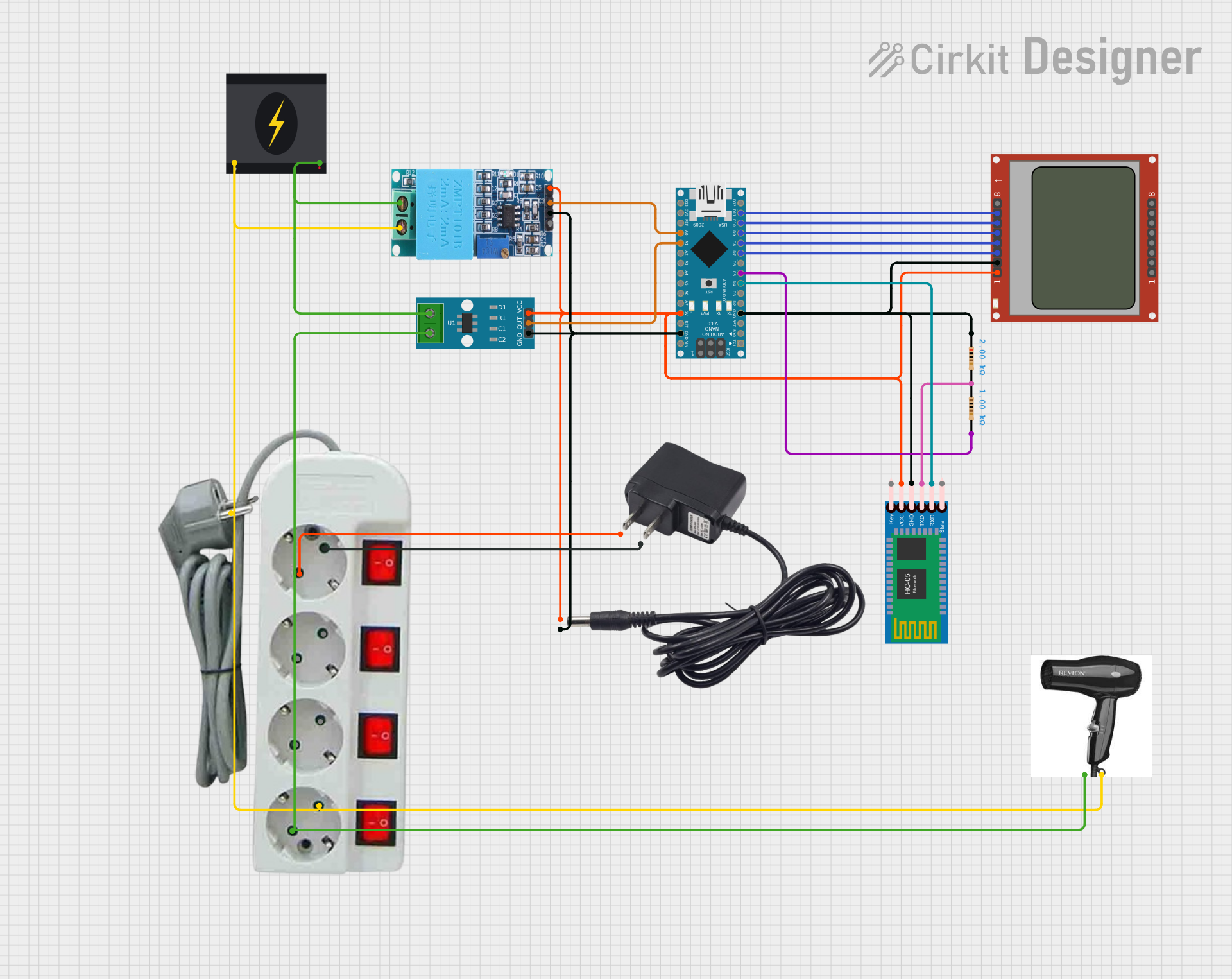
Explore Projects Built with watt meter
Common Applications and Use Cases
- Monitoring power consumption in household appliances
- Evaluating the efficiency of electrical devices
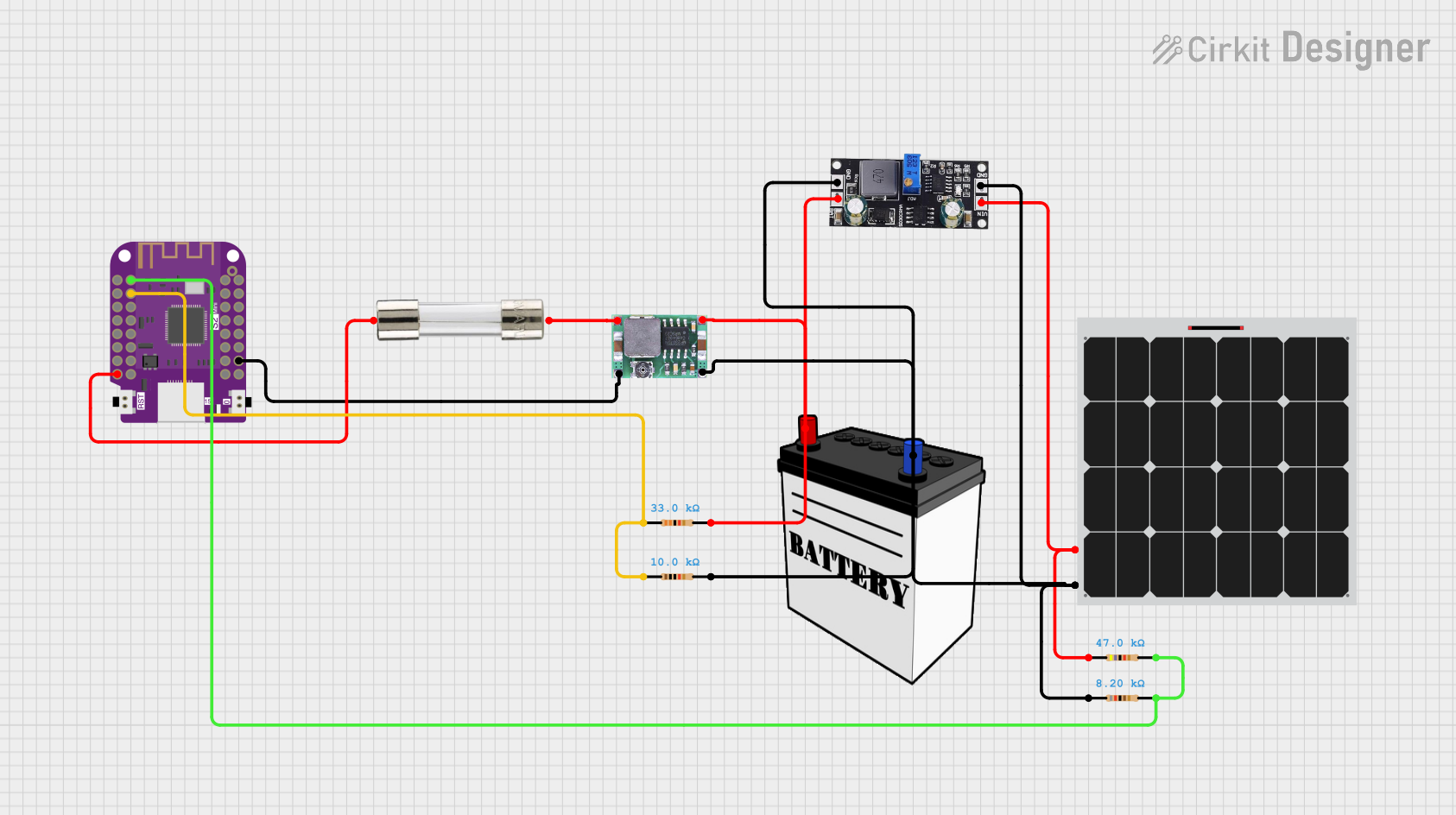
- Measuring power output in renewable energy systems (e.g., solar panels)
- Troubleshooting power-related issues in circuits
- Educational purposes in electronics and electrical engineering
Technical Specifications
The Arduino Watt Meter (Manufacturer Part ID: UNO) is designed to work seamlessly with Arduino-based systems. Below are the key technical details:
General Specifications
| Parameter | Value |
|---|---|
| Operating Voltage | 5V DC (via Arduino UNO) |
| Measurement Range | 0 - 250V AC/DC |
| Current Measurement | 0 - 20A |
| Power Measurement Range | 0 - 5000W |
| Accuracy | ±1% |
| Communication Interface | Analog or I2C (via sensors) |
Pin Configuration and Descriptions
The watt meter typically interfaces with an Arduino UNO using external sensors (e.g., voltage and current sensors). Below is an example pin configuration for a common setup:
Voltage Sensor (e.g., ZMPT101B)
| Pin Name | Description |
|---|---|
| VCC | Power supply (5V from Arduino) |
| GND | Ground |
| OUT | Voltage signal output |
Current Sensor (e.g., ACS712)
| Pin Name | Description |
|---|---|
| VCC | Power supply (5V from Arduino) |
| GND | Ground |
| OUT | Current signal output |
Usage Instructions
How to Use the Watt Meter in a Circuit
Connect the Voltage Sensor:
- Connect the
VCCpin of the voltage sensor to the 5V pin on the Arduino UNO. - Connect the
GNDpin of the voltage sensor to the GND pin on the Arduino UNO. - Connect the
OUTpin of the voltage sensor to an analog input pin (e.g., A0) on the Arduino UNO.
- Connect the
Connect the Current Sensor:
- Connect the
VCCpin of the current sensor to the 5V pin on the Arduino UNO. - Connect the
GNDpin of the current sensor to the GND pin on the Arduino UNO. - Connect the
OUTpin of the current sensor to another analog input pin (e.g., A1) on the Arduino UNO.
- Connect the
Load the Arduino Code:
- Use the provided Arduino code to calculate voltage, current, and power.
Power the Circuit:
- Supply power to the Arduino UNO and the circuit under test.
Monitor the Readings:
- View the calculated power readings on the Arduino Serial Monitor.
Important Considerations and Best Practices
- Ensure that the voltage and current sensors are rated for the expected range of your circuit.
- Avoid exceeding the maximum voltage and current ratings to prevent damage to the sensors or Arduino.
- Use proper isolation techniques when measuring high-voltage AC circuits.
- Calibrate the sensors for accurate readings.
Example Arduino Code
Below is an example Arduino sketch for measuring power using a voltage sensor and a current sensor:
// Watt Meter Example Code
// Measures voltage, current, and calculates power
// Connect voltage sensor to A0 and current sensor to A1

const int voltagePin = A0; // Analog pin for voltage sensor
const int currentPin = A1; // Analog pin for current sensor

float voltage = 0.0;       // Variable to store voltage reading
float current = 0.0;       // Variable to store current reading
float power = 0.0;         // Variable to store calculated power

void setup() {
  Serial.begin(9600); // Initialize serial communication
}

void loop() {
  // Read voltage sensor value
  int voltageRaw = analogRead(voltagePin);
  voltage = (voltageRaw * 5.0) / 1023.0; // Convert to voltage (assuming 5V ADC)

  // Read current sensor value
  int currentRaw = analogRead(currentPin);
  current = (currentRaw * 5.0) / 1023.0; // Convert to current (assuming 5V ADC)

  // Calculate power
  power = voltage * current;

  // Print readings to Serial Monitor
  Serial.print("Voltage: ");
  Serial.print(voltage);
  Serial.print(" V, Current: ");
  Serial.print(current);
  Serial.print(" A, Power: ");
  Serial.print(power);
  Serial.println(" W");

  delay(1000); // Wait 1 second before next reading
}
Troubleshooting and FAQs
Common Issues and Solutions
Incorrect Readings:
- Cause: Sensors are not calibrated.
- Solution: Calibrate the sensors using a known voltage and current source.
No Output on Serial Monitor:
- Cause: Serial communication is not initialized or incorrect COM port is selected.
- Solution: Ensure
Serial.begin(9600)is in the code and select the correct COM port in the Arduino IDE.
Overheating Sensors:
- Cause: Exceeding the maximum voltage or current rating.
- Solution: Verify that the circuit's voltage and current are within the sensor's specifications.
Fluctuating Power Readings:
- Cause: Electrical noise or unstable power supply.
- Solution: Use capacitors for noise filtering and ensure a stable power source.
FAQs
Q: Can this watt meter measure both AC and DC power?
A: Yes, with appropriate sensors, it can measure both AC and DC power. Ensure the sensors are compatible with the type of power being measured.
Q: How do I improve the accuracy of the readings?
A: Calibrate the sensors, use high-quality components, and minimize electrical noise in the circuit.
Q: Can I use this watt meter for high-power applications?
A: Yes, but ensure the sensors and Arduino are rated for the voltage and current levels in your application. Use external relays or transformers if necessary.
Q: Is this watt meter suitable for industrial use?
A: This setup is primarily for educational and hobbyist purposes. For industrial applications, consider using professional-grade watt meters.