How to Use DIN Switch Power Terminal: Examples, Pinouts, and Specs
Introduction
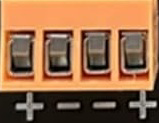
The DIN Switch Power Terminal is a terminal block designed for mounting on standard DIN rails. It is used to connect power supply lines to various electrical devices in a safe, reliable, and organized manner. This component is widely utilized in industrial automation, control panels, and electrical distribution systems. Its modular design allows for easy installation and maintenance, making it an essential component in modern electrical setups.
Explore Projects Built with DIN Switch Power Terminal


Explore Projects Built with DIN Switch Power Terminal
Common Applications and Use Cases
- Industrial control panels for connecting power lines to devices.
- Electrical distribution systems in factories and buildings.
- Automation systems requiring organized power connections.
- Renewable energy systems for managing power distribution.
- Any application requiring safe and modular power line connections.
Technical Specifications
Key Technical Details
- Rated Voltage: 250V to 1000V (varies by model)
- Rated Current: 10A to 125A
- Wire Size Compatibility: 0.2mm² to 35mm² (24 AWG to 2 AWG)
- Mounting Type: Standard DIN rail (35mm width)
- Material: Flame-retardant polyamide (UL94-V0)
- Operating Temperature: -40°C to +105°C
- Connection Type: Screw or spring clamp (depending on model)
- Color Options: Typically available in gray, blue, and yellow/green for grounding.
Pin Configuration and Descriptions
The DIN Switch Power Terminal does not have traditional "pins" like an IC but instead features connection points for wires. Below is a table describing the key connection points:
| Connection Point | Description |
|---|---|
| Input Terminal | Connects to the incoming power supply line. |
| Output Terminal | Connects to the outgoing power line for powering devices. |
| Ground Terminal | (Optional) Provides a connection point for grounding wires. |
| Test Point | (Optional) Allows for voltage or continuity testing without disconnecting wires. |
Usage Instructions
How to Use the Component in a Circuit
Mounting the Terminal Block:
- Secure the DIN Switch Power Terminal onto a 35mm DIN rail by snapping it into place.
- Ensure the terminal block is firmly attached to prevent movement during operation.
Connecting Wires:
- Strip the insulation from the wire ends (typically 6-10mm, depending on the terminal size).
- Insert the stripped wire into the input and output terminals.
- Tighten the screw or spring clamp to secure the wire. Avoid overtightening to prevent damage.
Grounding (if applicable):
- For models with a ground terminal, connect the grounding wire to the designated terminal (usually yellow/green).
Testing:
- Use the test point (if available) to verify voltage or continuity without disconnecting wires.
Powering the System:
- Once all connections are secure, power on the system and verify proper operation.
Important Considerations and Best Practices
- Wire Compatibility: Ensure the wire gauge matches the terminal's specifications to avoid loose connections or overheating.
- Torque Settings: Follow the manufacturer's recommended torque settings for screws to ensure secure connections.
- DIN Rail Compatibility: Verify that the DIN rail is of the standard 35mm width.
- Labeling: Use terminal markers or labels to identify connections for easier troubleshooting and maintenance.
- Safety: Always disconnect power before making or modifying connections.
Example: Connecting to an Arduino UNO
While the DIN Switch Power Terminal is not directly connected to an Arduino UNO, it can be used to distribute power to the Arduino and other devices in a project. Below is an example of how to use the terminal block in such a setup:
// Example Arduino code for controlling a relay connected to a power terminal
// This assumes the power terminal is distributing power to the relay and Arduino.

const int relayPin = 7; // Pin connected to the relay control input

void setup() {
  pinMode(relayPin, OUTPUT); // Set the relay pin as an output
  digitalWrite(relayPin, LOW); // Ensure the relay is off initially
}

void loop() {
  digitalWrite(relayPin, HIGH); // Turn the relay on
  delay(1000); // Keep it on for 1 second
  digitalWrite(relayPin, LOW); // Turn the relay off
  delay(1000); // Keep it off for 1 second
}

// Note: Ensure the power terminal is properly connected to the relay and Arduino.
// The terminal block should distribute power from the main supply to the relay module
// and the Arduino board. Always double-check connections for safety.
Troubleshooting and FAQs
Common Issues and Solutions
Loose Connections:
- Issue: Wires are not securely held in the terminal.
- Solution: Check that the wire gauge matches the terminal's specifications and tighten the screw or spring clamp properly.
Overheating:
- Issue: The terminal block becomes hot during operation.
- Solution: Ensure the current does not exceed the terminal's rated capacity. Use wires of appropriate gauge.
DIN Rail Mounting Issues:
- Issue: The terminal block does not fit securely on the DIN rail.
- Solution: Verify that the DIN rail is of the standard 35mm width and free of obstructions.
Intermittent Connections:
- Issue: Devices connected to the terminal block lose power intermittently.
- Solution: Inspect all connections for loose wires or corrosion. Retighten or replace as needed.
FAQs
Q: Can I use this terminal block for DC and AC power?
- A: Yes, the DIN Switch Power Terminal is suitable for both DC and AC power, provided the voltage and current ratings are not exceeded.
Q: How do I identify the ground terminal?
- A: The ground terminal is typically marked with a yellow/green color or a grounding symbol.
Q: Can I stack multiple terminal blocks on the same DIN rail?
- A: Yes, multiple terminal blocks can be mounted side by side on the same DIN rail for modular and organized connections.
Q: Is it safe to use this terminal block outdoors?
- A: The terminal block is designed for indoor use. For outdoor applications, ensure it is housed in a weatherproof enclosure.
By following this documentation, you can effectively use the DIN Switch Power Terminal in your electrical and automation projects.