
How to Use SSOP20: Examples, Pinouts, and Specs
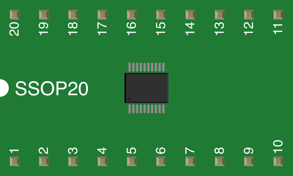
 Design with SSOP20 in Cirkit Designer
Introduction
The SSOP20 (Shrink Small Outline Package with 20 pins) is a type of surface-mount integrated circuit (IC) package. It is characterized by its compact size, low profile, and high pin density, making it ideal for applications where space is a critical factor. The SSOP20 is commonly used in consumer electronics, communication devices, and industrial equipment. Its small footprint and reliable performance make it a popular choice for high-density circuit designs.
Explore Projects Built with SSOP20
 Open Project in Cirkit Designer
 Open Project in Cirkit Designer
 Open Project in Cirkit Designer
 Open Project in Cirkit Designer
Explore Projects Built with SSOP20
Open Project in Cirkit DesignerOpen Project in Cirkit DesignerOpen Project in Cirkit DesignerOpen Project in Cirkit DesignerCommon Applications
- Microcontrollers and digital signal processors (DSPs)
- Memory modules (e.g., EEPROM, Flash)
- Analog-to-digital converters (ADCs) and digital-to-analog converters (DACs)
- Power management ICs
- Communication interfaces (e.g., UART, I2C, SPI)
Technical Specifications
Key Technical Details
- Package Type: SSOP (Shrink Small Outline Package)
- Number of Pins: 20
- Pin Pitch: 0.65 mm (distance between adjacent pins)
- Body Width: 5.3 mm (typical)
- Body Length: 7.2 mm (typical)
- Height: 1.75 mm (maximum)
- Mounting Type: Surface-mount technology (SMT)
- Thermal Resistance: Varies by IC, typically 50–100 °C/W
- Operating Temperature Range: -40 °C to +125 °C (depending on the IC inside the package)
Pin Configuration and Descriptions
The SSOP20 package has 20 pins, which are typically arranged in two parallel rows of 10 pins each. The specific pin functions depend on the IC housed within the package. Below is a generic example of pin configuration for a microcontroller in an SSOP20 package:
| Pin Number | Pin Name | Description |
|---|---|---|
| 1 | VCC | Power supply (positive voltage input) |
| 2 | GND | Ground (0V reference) |
| 3 | RESET | Reset input |
| 4 | GPIO1 | General-purpose input/output pin 1 |
| 5 | GPIO2 | General-purpose input/output pin 2 |
| 6 | TX | UART transmit pin |
| 7 | RX | UART receive pin |
| 8 | SCL | I2C clock line |
| 9 | SDA | I2C data line |
| 10 | PWM1 | Pulse-width modulation output 1 |
| 11 | PWM2 | Pulse-width modulation output 2 |
| 12 | ADC1 | Analog-to-digital converter input 1 |
| 13 | ADC2 | Analog-to-digital converter input 2 |
| 14 | SPI_MOSI | SPI master-out, slave-in |
| 15 | SPI_MISO | SPI master-in, slave-out |
| 16 | SPI_SCK | SPI clock |
| 17 | SPI_CS | SPI chip select |
| 18 | INT1 | External interrupt input 1 |
| 19 | INT2 | External interrupt input 2 |
| 20 | NC | No connection (reserved for future use) |
Note: The actual pinout may vary depending on the specific IC inside the SSOP20 package. Always refer to the datasheet of the IC for accurate pin descriptions.
Usage Instructions
How to Use the SSOP20 in a Circuit
- PCB Design: Ensure your PCB layout matches the SSOP20 footprint. The pin pitch is 0.65 mm, so precise solder pad spacing is critical.
- Soldering: Use surface-mount soldering techniques, such as reflow soldering, for reliable connections. A solder stencil is recommended for applying solder paste.
- Power Supply: Verify the voltage and current requirements of the IC inside the SSOP20 package. Connect the VCC and GND pins to the appropriate power source.
- Signal Connections: Connect the signal pins (e.g., GPIO, UART, I2C, SPI) to the corresponding components in your circuit.
- Bypass Capacitors: Place decoupling capacitors (e.g., 0.1 µF) close to the VCC pin to reduce noise and stabilize the power supply.
Important Considerations and Best Practices
- Thermal Management: Ensure adequate heat dissipation, especially for high-power ICs. Use thermal vias or a heat sink if necessary.
- ESD Protection: Handle the SSOP20 package with care to avoid electrostatic discharge (ESD) damage. Use an anti-static wrist strap and mat during assembly.
- Pin Alignment: Double-check the orientation of the SSOP20 package before soldering. Pin 1 is typically marked with a dot or notch on the package.
Example: Connecting an SSOP20 Microcontroller to an Arduino UNO
If the SSOP20 package contains a microcontroller, you can interface it with an Arduino UNO using I2C. Below is an example Arduino sketch:
#include <Wire.h> // Include the Wire library for I2C communication

#define SSOP20_ADDRESS 0x40 // Replace with the actual I2C address of the SSOP20 IC

void setup() {
  Wire.begin(); // Initialize I2C communication
  Serial.begin(9600); // Start serial communication for debugging
  Serial.println("Initializing SSOP20...");
}

void loop() {
  Wire.beginTransmission(SSOP20_ADDRESS); // Start communication with SSOP20
  Wire.write(0x01); // Example: Send a command or data to the SSOP20 IC
  Wire.endTransmission(); // End the transmission

  delay(1000); // Wait for 1 second before repeating
}
Note: Replace
SSOP20_ADDRESSand theWire.write()command with values specific to your SSOP20 IC.
Troubleshooting and FAQs
Common Issues
- Incorrect Pin Connections: If the SSOP20 IC does not function as expected, verify that all pins are connected correctly according to the datasheet.
- Soldering Defects: Cold solder joints or solder bridges between pins can cause malfunction. Inspect the soldering under a microscope.
- Overheating: Excessive heat during soldering or operation can damage the IC. Use proper thermal management techniques.
Solutions and Tips
- Issue: The IC is not responding to I2C commands.
- Solution: Check the I2C address and ensure pull-up resistors (e.g., 4.7 kΩ) are connected to the SDA and SCL lines.
- Issue: The circuit is unstable or noisy.
- Solution: Add decoupling capacitors near the power pins and ensure a clean power supply.
- Issue: Pins are shorted after soldering.
- Solution: Use solder wick or a desoldering pump to remove excess solder.
FAQs
- Can I hand-solder an SSOP20 package?
- Yes, but it requires precision and a fine-tipped soldering iron. Use flux to prevent solder bridges.
- What is the maximum current the SSOP20 package can handle?
- This depends on the IC inside the package. Refer to the IC's datasheet for current ratings.
- How do I identify Pin 1 on the SSOP20 package?
- Pin 1 is typically marked with a dot, notch, or beveled edge on the package.
By following this documentation, you can effectively integrate and troubleshoot SSOP20 components in your electronic designs.